Scanner calibration 101

A few years ago I was able to run the k4050 plugin up to the point where it fails to detect any scanners on the SCSI bus as I have not connected the scanner to the SCSI.

Over the last few years I was given copies of the mac 8.6 software (diagnostics) the sun PIW installers, and recently the service manual. This made me take another look at the diagnostics program for mac os 8/9. The service manual was targeted to the Sun Piw. There is a lot of Piw code in the Photoshop plugin driver.

The main issue with the Mac os 8 diagnostic program was that it was zipped. This removed all the resource data effectively destroying the program. A Hex dump of the remaining part of the app shows it as PowerPC PEF built with mangled name symbols. This would imply that most of the app is still there and might be recovered by synthesizing the resource fork.

The same custom dissembler written for the photoshop plugin was used to dump the diagnostic. A search online found a copy of Metrowerks CodeWarrior that seems to match the libraries used. An example app was built and the resource skeleton was added to the resource fork. Type and creator set to application.

Of course the menus are incorrect and there are no windows. But the app runs. It even generates a debug log though the try/catch mechanism. Placing a breakpoint just before the ‘wrong scanner’ exit allows tracing. Time to read up on CodeWarrior PPob classes. The code also uses some Rouge Wave string classes. The PCD4050 plugin also uses this library (available from the Sun linux IDE.) That library has not been updated since 1996. Interesting to see that it has #ifdef definitions for MacOS and CodeWarrior.

Since these apps are compiled with debug tags with mangled names, it is almost easy to read the code. The code also used a try/catch error handler. This will sometimes even give the filename and line number of the source code. About 40 to 50 percent of the code is power-plant application framework. Given that many of the remaining classes start with Piw, this code is basically ported sun code.

The SCIS driver classes are preceded with DIS. I have been unable to find this class as a library. Most likely this was an in house library.

The diagnostic and calibration programs used special strips of film exposed with a test pattern. The manual gives the layout of these patches along with some YCC values of a set of patches that are different on a given target.

The Mac OS 8.6 zip archive contains a smi of a calibration run (and logs) these did not use resource forks. The smi will mount and is an image of the calibration floppy. The files in the system extensions folder seem flat and look to contain matrix data for a 4050 scanner.

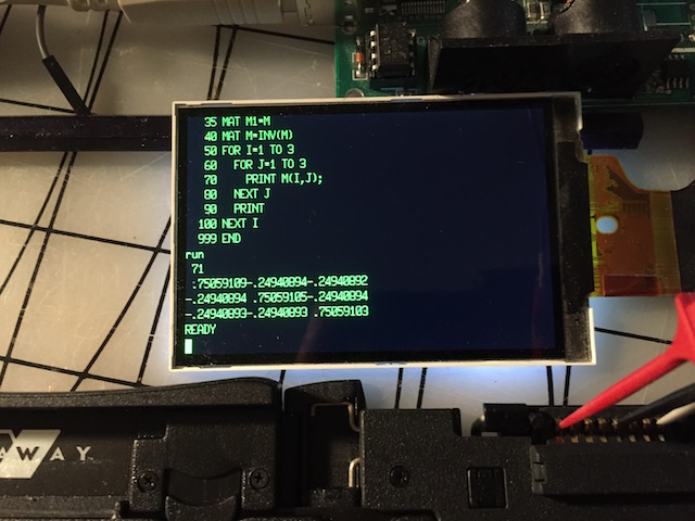
The resulting tables give RGB values. Probably in volts. The upper ranges are over 2048. but quite a bit less than 4096. Scaling with a 4096 (2^12) results in the patches displaying really dark on the display. Inverting the RGB, and one can see washed out color patches.

It is probable that these calibration strips have all been lost or destroyed. There is no evidence any were ever online. Chances of finding them are slim to none. I suspect the handful of people who have contacted me represents most of those who may retain a slight interest in this obsolete tech.

In the meantime, here is a bit of an update as to what I have found and done.

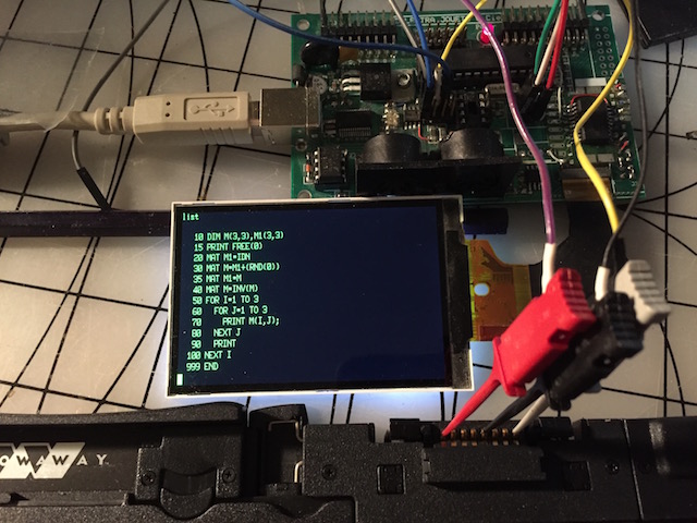
Entering the logged result values into a simple postscript program shows this grid matches the Illustrations in the service manual. This is a way a calibration film strip could be made. If one could photograph the resulting postscript output then the results could be photographed onto film. I have not done film photography (other than with the stereo realist in years.)

With my searches for data relating to PhotoCD I know that old cameras are cheap and sold in bulk. A visit to the local electronics recycler has tubs of them. Mostly digital, but quite a few film cameras as well. Some even loaded with film. I knew I had an old can of expired film. All I would need to do would be to expose it with precisely placed color. patches. Something postscript can do. I purchased a dozen or so cameras. Some had film jammed inside.

I learned about something worse than photo CD. APS! How could I have missed APS and Advantix? Oh no, a totally new distraction. I now have half a dozen APS cameras. And a completely new distraction. I suspect there will be more on this later. These cameras are a world unto themselves. At the time of this blog writing, they can be had cheap and old film and processing remains available for others who like really failed products.

While these cameras are interesting, they do not take normal film. Sort of a film data tape hybrid. They do contain some interesting motors and gearing. This film is no longer manufactured. Some of the cameras contained partial rolls. I found that the local lab can process it.

I also found a school science project supplier online. Too bad I did not have access to this sort of thing 25 years ago. They sell simple spectrometers, filters and diffraction gratings. I got out my old copy stand and rigged it with LED lighting.

I used an old iPhone to simply photograph the filter slides. I then took the APS camera and shot the rest of the roll through each filter against my monitor background. The results are promising. The film came back and each frame has the inverse of the color. I have not attempted to scan the returned film as the Kodak scanner has a long way to go. The old USB scanner i have gives less than satisfactory results.

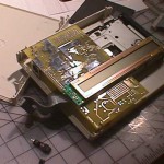
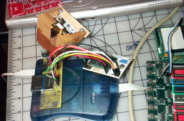
The next step is to modify an old Olympus film camera that I gutted. This was a point an shoot camera. A digital camera back would probably be more productive. This way is so much more interesting. An Arduino should be able to control the shutter solenoid and the film advance.

A lot of the work over the last couple of years has been dissembling and re-construction the plugin code. This sort of effort does not really lend itself into frequent blog postings. I sort of swap between dissembling camera hardware, and dissembling munged obsolete driver code. I also actively scan piano rolls with custom hardware. So these efforts do have some general use.

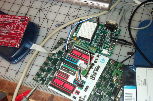
I have a couple of vintage macs which I use for tracing code. The plugin and the diagnostics are not small programs, with the plug in clocking in at near 2MB. The surviving diagnostic code is about half that size.

There was never a mac driver for the Film scanner 2000. I have not found any references to a DIS SCSI library. DIS is the class name of the SCSI library used. Other classes are PTS and PIW.

I would be really surprised if anyone has one of these units working anywhere. I check once a month for parts or more documentation. I think only three or so people ever contacted me. (but they all did have most useful stuff.)

I have also been hesitant to apply any power or signals to the SCSI port as I only have one film scanner. Research has directed to something called RaSCSI, which looks like a promising way to emulate the interface. This way I can also create a bridge to Ethernet, which would be a more practical way to communicate with the scanner.

I have yet to ring out an adapter to the MD50 connector from the HDI30 on the laptop. I did find I had a cable that goes to the flatbed Apple Color scanner which I still have. Another project for another blog.

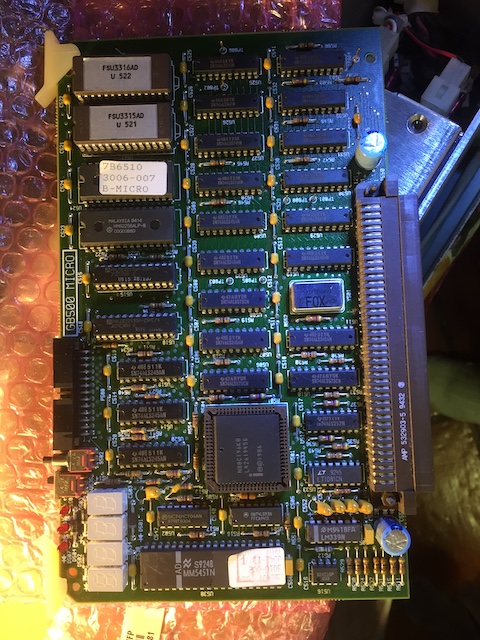
When the pcd 2000 scanner (or the other variations) are connected the host program downloads a hex file. While there is quite a sophisticated controller unit based on the 80C196KB. The actual program is downloaded every time.

The service manuals are quite informative about this operation. There is also an online paper (which is behind a paywall) that also covers what these boards do. The heart of this system is an ASIC called a normalizer. This term is also used for programs that convert postscript to PDF. There must also be quite a bit of ram on this board as the raw images are 18megapixels. The user/operator is well protected from this raw data. It all seems to be about the density.

The mac OS 8 image does contain a hex file called 4050.hex While there are strings that refer to other scanners like the 2000, these are used in the wrong scanner dialog. Another reason I have not connected the scanner is the lack of the correct microcode file.

The PIW install disks contain more hex files. One is called scanner.hex and the other metaphor.hex. Dumping these shows the version strings. There are a lot of references to metaphor in the OS 8 code. It is almost it’s own class. Metaphor seems to be the 4045/4050 driver.

Scanner.hex is the 2000 code. I modified the postscript table driven disassembler that I have used on 8080, avr,m68k and powerpc to do 80C196. The first results were a bit off as I had used the wrong chip variant, which has different registers. When the 80C196 register table was used, the code started making sense.

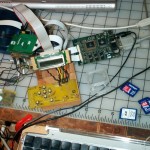
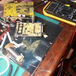
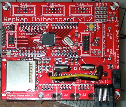
The main processor board is mostly latches. There is some SRAM and a seven segment display. (this board is shown in an earlier blog.) An interesting thing is that the code regularly pushes 4 digit hex numbers onto the stack. These do not seem to be memory locations.

By chance I noticed that they were the same range as the error codes in the service manual. These codes should show on the 7 segment display. The sophistication of this is quite impressive. Too bad most consumer equipment does not do these types of boundary checks any more. I think they really did think this tech would last the next hundred years.

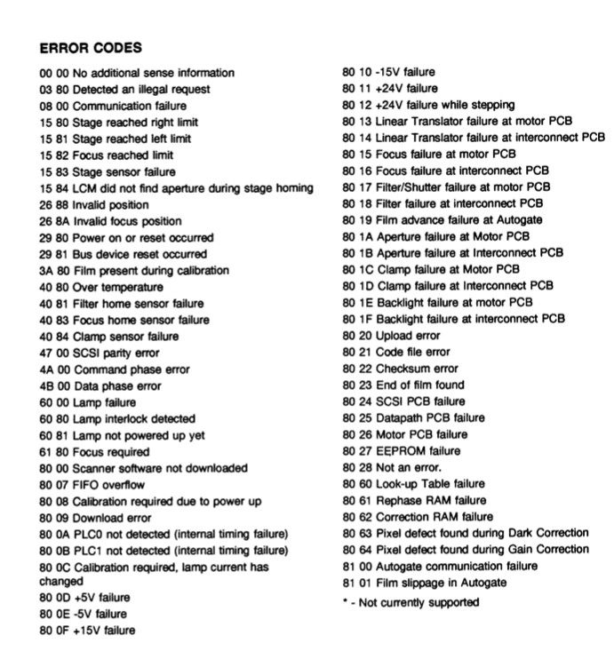
by adding these numbers to a table in the disassembler one can see the error handler. The timer overflow basically sets counters. So some sort of kernel is being used with the state queued.

D0 00C80B: C8E0		'..'	prepError:PUSH	.stack_frame.	looks like error handler setup
C0 00C80D: A018E0	'...'	          LD	.stack_frame.,SP	; .stack_frame. <- SP
C0 00C810: C8A6		'..'	          PUSH	R.A6
C0 00C812: A3E0041C	'....'	          LD	AX,000004H[.stack_frame.]	; AX <- Var2
C0 00C816: 8981291C	'..).'	          CMP	AX,#0x2981	; Bus device reset
C0 00C81A: D726		'.&'	          JNE	L000016	; PC <- 00C842 PC + 38 (00C81C)
D0 00C81C: C301560700	'..V..'	L000017:  ST	ZERO_REG,000756H[ZERO_REG]	;  .datamemL. MEM_WORD(000756) <- ZERO_REG
C0 00C821: 11A6		'..'	          CLRB	R.A6
C0 00C823: 2018		' .'	          SJMP	L000018	; PC <- 00C83D PC + 24 (00C825)
D0 00C825: ACA61C	'...'	L000019:  LDBZE	AX,R.A6	; AX <- R.A6
C0 00C828: 09011C	'...'	          SHL	AX, #0x1
C0 00C82B: C71D460700	'..F..'	          STB	ZERO_REG,000746H[AX]	; MEM_BYTE(AX + 1862) <- ZERO_REG
C0 00C830: ACA61C	'...'	          LDBZE	AX,R.A6	; AX <- R.A6
C0 00C833: 09011C	'...'	          SHL	AX, #0x1
C0 00C836: C71D470700	'..G..'	          STB	ZERO_REG,000747H[AX]	; MEM_BYTE(AX + 1863) <- ZERO_REG
C0 00C83B: 17A6		'..'	          INCB	R.A6
D0 00C83D: 9908A6	'...'	L000018:  CMPB	R.A6,#0x08	; R.A6 == 8
C0 00C840: D3E3		'..'	          JNC	L000019	; PC <- 00C825 PC + -29 (00C842)
D0 00C842: A30156071C	'..V..'	L000016:  LD	AX,000756H[ZERO_REG]	; AX <-  .datamemL. MEM_WORD(000756)
C0 00C847: 8907001C	'....'	          CMP	AX,#0x0007	; AX == 7
C0 00C84B: DB2F		'./'	          JC	L000020	; PC <- 00C87C PC + 47 (00C84D)
D0 00C84D: 450400E01C	'E....'	L000021:  ADD	AX,.stack_frame.,#0x0004	; AX = .stack_frame. + 4
C0 00C852: C81C		'..'	          PUSH	AX
C0 00C854: A30156071C	'..V..'	          LD	AX,000756H[ZERO_REG]	; AX <-  .datamemL. MEM_WORD(000756)
C0 00C859: 6107001C	'a...'	          AND	AX,#0x0007	; AX &= 7
C0 00C85D: 09011C	'...'	          SHL	AX, #0x1
C0 00C860: 6546071C	'eF..'	          ADD	AX,#0x0746	; AX += 1862
C0 00C864: C81C		'..'	          PUSH	AX
C0 00C866: EF6856	'.hV'	          LCALL	L000022	; (00C869 + 22120) -> 001ED1
C0 00C869: 65040018	'e...'	          ADD	SP,#0x0004	; SP += 4
C0 00C86D: A30156071C	'..V..'	          LD	AX,000756H[ZERO_REG]	; AX <-  .datamemL. MEM_WORD(000756)
C0 00C872: 4501001C1E	'E....'	          ADD	BX,AX,#0x0001	; BX = AX + 1
C0 00C877: C30156071E	'..V..'	          ST	BX,000756H[ZERO_REG]	;  .datamemL. MEM_WORD(000756) <- BX
D0 00C87C: A30156071C	'..V..'	L000020:  LD	AX,000756H[ZERO_REG]	; AX <-  .datamemL. MEM_WORD(000756)
C0 00C881: 051C		'..'	          DEC	AX
C0 00C883: 6107001C	'a...'	          AND	AX,#0x0007	; AX &= 7
C0 00C887: CCA6		'..'	          POP	R.A6
C0 00C889: CCE0		'..'	          POP	.stack_frame.
C0 00C88B: F0		'.'	          RET	

Some of the startup code is also of interest. Most likely the various communication sections are memory mapped in the higher address space. Curiously there is not a lot of windowing. This may be a result of the compiler used as only a subset of instructions are common.

L000003:  SUB	SP,#0x0004	; SP -= 4
C0 00965B: C8E0		'..'	          PUSH	.stack_frame.
C0 00965D: A018E0	'...'	          LD	.stack_frame.,SP	; .stack_frame. <- SP
C0 009660: C872		'.r'	          PUSH	R.72
C0 009662: C874		'.t'	          PUSH	R.74
C0 009664: A100D072	'...r'	          LD	R.72,#0xD000	; R.72 <--12288
C0 009668: BD441C	'.D.'	          LDBSE	AX,#0x44	; AX <-68
C0 00966B: C301E4001C	'.....'	          ST	AX,0000E4H[ZERO_REG]	; REG(R.E4) MEM_WORD(0000E4) <- AX
C0 009670: C2721C	'.r.'	          ST	[R.72],AX	; MEM_WORD(R.72) <- AX
C0 009673: A100D272	'...r'	          LD	R.72,#0xD200	; R.72 <--11776
C0 009677: A100801C	'....'	          LD	AX,#0x8000	; Scanner software not downloaded
C0 00967B: C301E6001C	'.....'	          ST	AX,0000E6H[ZERO_REG]	; REG(R.E6) MEM_WORD(0000E6) <- AX
C0 009680: C2721C	'.r.'	          ST	[R.72],AX	; MEM_WORD(R.72) <- AX
C0 009683: A100D472	'...r'	          LD	R.72,#0xD400	; R.72 <--11264
C0 009687: C301E80000	'.....'	          ST	ZERO_REG,0000E8H[ZERO_REG]	; REG(R.E8) MEM_WORD(0000E8) <- ZERO_REG
C0 00968C: A301E8001C	'.....'	          LD	AX,0000E8H[ZERO_REG]	; AX <- REG(R.E8) MEM_WORD(0000E8)
C0 009691: C2721C	'.r.'	          ST	[R.72],AX	; MEM_WORD(R.72) <- AX
C0 009694: A100D672	'...r'	          LD	R.72,#0xD600	; R.72 <--10752
C0 009698: C301EA0000	'.....'	          ST	ZERO_REG,0000EAH[ZERO_REG]	; REG(R.EA) MEM_WORD(0000EA) <- ZERO_REG
C0 00969D: A301EA001C	'.....'	          LD	AX,0000EAH[ZERO_REG]	; AX <- REG(R.EA) MEM_WORD(0000EA)
C0 0096A2: C2721C	'.r.'	          ST	[R.72],AX	; MEM_WORD(R.72) <- AX
C0 0096A5: A100D872	'...r'	          LD	R.72,#0xD800	; R.72 <--10240
C0 0096A9: C301EC0000	'.....'	          ST	ZERO_REG,0000ECH[ZERO_REG]	; REG(R.EC) MEM_WORD(0000EC) <- ZERO_REG
C0 0096AE: A301EC001C	'.....'	          LD	AX,0000ECH[ZERO_REG]	; AX <- REG(R.EC) MEM_WORD(0000EC)
C0 0096B3: C2721C	'.r.'	          ST	[R.72],AX	; MEM_WORD(R.72) <- AX
C0 0096B6: A100DA72	'...r'	          LD	R.72,#0xDA00	; R.72 <--9728
C0 0096BA: C301EE0000	'.....'	          ST	ZERO_REG,0000EEH[ZERO_REG]	; REG(R.EE) MEM_WORD(0000EE) <- ZERO_REG
C0 0096BF: A301EE001C	'.....'	          LD	AX,0000EEH[ZERO_REG]	; AX <- REG(R.EE) MEM_WORD(0000EE)
C0 0096C4: C2721C	'.r.'	          ST	[R.72],AX	; MEM_WORD(R.72) <- AX
C0 0096C7: A120DC1C	'. ..'	          LD	AX,#0xDC20	; AX <--9184
C0 0096CB: C3E0021C	'....'	          ST	AX,000002H[.stack_frame.]	; Var1 <- AX
C0 0096CF: B103CA	'...'	          LDB	R.CA,#0x03	; R.CA <- 3
C0 0096D2: C61CCA	'...'	          STB	[AX],R.CA	; MEM_BYTE(AX) <- R.CA
C0 0096D5: A100DE72	'...r'	          LD	R.72,#0xDE00	; R.72 <--8704
C0 0096D9: C301F20000	'.....'	          ST	ZERO_REG,0000F2H[ZERO_REG]	; REG(R.F2) MEM_WORD(0000F2) <- ZERO_REG
C0 0096DE: A301F2001C	'.....'	          LD	AX,0000F2H[ZERO_REG]	; AX <- REG(R.F2) MEM_WORD(0000F2)
C0 0096E3: C2721C	'.r.'	          ST	[R.72],AX	; MEM_WORD(R.72) <- AX
C0 0096E6: A301F2001C	'.....'	          LD	AX,0000F2H[ZERO_REG]	; AX <- REG(R.F2) MEM_WORD(0000F2)
C0 0096EB: 8100801C	'....'	          OR	AX,#0x8000	; Scanner software not downloaded
C0 0096EF: C301F2001C	'.....'	          ST	AX,0000F2H[ZERO_REG]	; REG(R.F2) MEM_WORD(0000F2) <- AX
C0 0096F4: C2721C	'.r.'	          ST	[R.72],AX	; MEM_WORD(R.72) <- AX
C0 0096F7: A1401F1C	'.@..'	          LD	AX,#0x1F40	; AX <-8000
C0 0096FB: C30122051C	'.."..'	          ST	AX,000522H[ZERO_REG]	;  .datamemL. MEM_WORD(000522) <- AX
C0 009700: B11003	'...'	          LDB	AD_RESULT_H,#0x10	; AD_RESULT_H <- 16
C0 009703: B11015	'...'	          LDB	IOS0,#0x10	; IOS0 <- 16
C0 009706: B12616	'.&.'	          LDB	IOS1,#0x26	; IOS1 <- 38
C0 009709: B1010B	'...'	          LDB	TiMER1.H,#0x01	; TiMER1.H <- 1
C0 00970C: B1260E	'.&.'	          LDB	IOPORT0,#0x26	; IOPORT0 <- 38
C0 00970F: B1800E	'...'	          LDB	IOPORT0,#0x80	; IOPORT0 <- 128
C0 009712: B10D11	'...'	          LDB	SP_STAT,#0x0D	; SP_STAT <- 13
C0 009715: 910508	'...'	          ORB	INT_MASK,#0x05	; INT_MASK |= 5
C0 009718: 911213	'...'	          ORB	INT_MASK1,#0x12	; INT_MASK1 |= 18
C0 00971B: 11CF		'..'	          CLRB	R.CF
C0 00971D: 11D0		'..'	          CLRB	R.D0
C0 00971F: 11CE		'..'	          CLRB	R.CE
C0 009721: B1201C	'. .'	          LDB	AX,#0x20	; AX <- 32
C0 009724: C70175061C	'..u..'	          STB	AX,000675H[ZERO_REG]	;  .datamemL. MEM_BYTE(000675) <- AX
C0 009729: B101D1	'...'	          LDB	R.D1,#0x01	; R.D1 <- 1
C0 00972C: C701A10B00	'.....'	          STB	ZERO_REG,000BA1H[ZERO_REG]	;  .datamemL. MEM_BYTE(000BA1) <- ZERO_REG
C0 009731: EF5831	'.X1'	          LCALL	L000004	; (009734 + 12632) -> 00C88C
C0 009734: EFA331	'..1'	          LCALL	L000012	; (009737 + 12707) -> 00C8DA
C0 009737: C701E30000	'.....'	          STB	ZERO_REG,0000E3H[ZERO_REG]	; REG(R.E3) MEM_BYTE(0000E3) <- ZERO_REG
C0 00973C: EFAE88	'...'	          LCALL	L000013	; (00973F + -30546) -> 001FED
C0 00973F: 9BE00800	'....'	          CMPB	ZERO_REG,000008H[.stack_frame.]	; Var4 == ZERO_REG
C0 009743: D730		'.0'	          JNE	L000014	; PC <- 009775 PC + 48 (009745)
D0 009745: C98029	'..)'	L000015:  PUSH	#0x2980	; Power on or reset occurred
C0 009748: EFC030	'..0'	          LCALL	prepError	; (00974B + 12480) -> 00C80B
C0 00974B: 65020018	'e...'	          ADD	SP,#0x0002	; SP += 2
C0 00974F: 51080F1C	'Q...'	          ANDB	AX,IOPORT1,#0x08	; AX = IOPORT1 & 8
C0 009753: 99081C	'...'	          CMPB	AX,#0x08	; AX == 8
C0 009756: D70A		'..'	          JNE	L002049	; PC <- 009762 PC + 10 (009758)
D0 009758: C90080	'...'	L002050:  PUSH	#0x8000	; Scanner software not downloaded
C0 00975B: EFAD30	'..0'	          LCALL	prepError	; (00975E + 12461) -> 00C80B .processed.
C0 00975E: 65020018	'e...'	          ADD	SP,#0x0002	; SP += 2
D0 009762: C90600	'...'	L002049:  PUSH	#0x0006	; MEM_WORD(SP -= 2) <- 6
C0 009765: EF7831	'.x1'	          LCALL	L000132	; (009768 + 12664) -> 00C8E0 .processed.
C0 009768: 65020018	'e...'	          ADD	SP,#0x0002	; SP += 2
C0 00976C: C701690600	'..i..'	          STB	ZERO_REG,000669H[ZERO_REG]	;  .datamemL. MEM_BYTE(000669) <- ZERO_REG
C0 009771: A1401FB8	'.@..'	          LD	R.B8,#0x1F40	; R.B8 <-8000
D0 009775: C800		'..'	L000014:  PUSH	ZERO_REG
C0 009777: C800		'..'	          PUSH	ZERO_REG
C0 009779: EFEC2A	'..*'	          LCALL	L000023	; (00977C + 10988) -> 00C268
C0 00977C: 65040018	'e...'	          ADD	SP,#0x0004	; SP += 4
C0 009780: C800		'..'	          PUSH	ZERO_REG
C0 009782: C800		'..'	          PUSH	ZERO_REG
C0 009784: EFE12A	'..*'	          LCALL	L000023	; (009787 + 10977) -> 00C268 .processed.
C0 009787: 65040018	'e...'	          ADD	SP,#0x0004	; SP += 4
C0 00978B: C95C7C	'.\|'	          PUSH	#0x7C5C	; MEM_WORD(SP -= 2) <- 31836
C0 00978E: C9785C	'.x\'	          PUSH	#0x5C78	; MEM_WORD(SP -= 2) <- 23672
C0 009791: EFD42A	'..*'	          LCALL	L000023	; (009794 + 10964) -> 00C268 .processed.
C0 009794: 65040018	'e...'	          ADD	SP,#0x0004	; SP += 4
C0 009798: C701680600	'..h..'	          STB	ZERO_REG,000668H[ZERO_REG]	;  .datamemL. MEM_BYTE(000668) <- ZERO_REG
C0 00979D: C90100	'...'	          PUSH	#0x0001	; MEM_WORD(SP -= 2) <- 1
C0 0097A0: EF53F5	'.S.'	          LCALL	L000034	; (0097A3 + -2733) -> 008CF6
C0 0097A3: 65020018	'e...'	          ADD	SP,#0x0002	; SP += 2
C0 0097A7: EFC2F5	'...'	          LCALL	L000040	; (0097AA + -2622) -> 008D6C
C0 0097AA: C701440600	'..D..'	          STB	ZERO_REG,000644H[ZERO_REG]	;  .datamemL. MEM_BYTE(000644) <- ZERO_REG
C0 0097AF: C701740600	'..t..'	          STB	ZERO_REG,000674H[ZERO_REG]	;  .datamemL. MEM_BYTE(000674) <- ZERO_REG
C0 0097B4: EF5A18	'.Z.'	          LCALL	L000050	; (0097B7 + 6234) -> 00B011
C0 0097B7: 881C00	'...'	          CMP	ZERO_REG,AX	; ZERO_REG == AX
C0 0097BA: DF0A		'..'	          JE	L001816	; PC <- 0097C6 PC + 10 (0097BC)
D0 0097BC: C92780	'.'.'	L001817:  PUSH	#0x8027	; EEPROM failure
C0 0097BF: EF4930	'.I0'	          LCALL	prepError	; (0097C2 + 12361) -> 00C80B .processed.
C0 0097C2: 65020018	'e...'	          ADD	SP,#0x0002	; SP += 2
D0 0097C6: C800		'..'	L001816:  PUSH	ZERO_REG
C0 0097C8: C90400	'...'	          PUSH	#0x0004	; MEM_WORD(SP -= 2) <- 4
C0 0097CB: EF467F	'.F'	          LCALL	L000107	; (0097CE + 32582) -> 001714 .processed.
C0 0097CE: 65040018	'e...'	          ADD	SP,#0x0004	; SP += 4
C0 0097D2: C96008	'.`.'	          PUSH	#0x0860	; MEM_WORD(SP -= 2) <- 2144
C0 0097D5: C800		'..'	          PUSH	ZERO_REG
C0 0097D7: EF4A79	'.Jy'	          LCALL	L000887	; (0097DA + 31050) -> 001124 .processed.
C0 0097DA: 65040018	'e...'	          ADD	SP,#0x0004	; SP += 4
C0 0097DE: C9D007	'...'	          PUSH	#0x07D0	; MEM_WORD(SP -= 2) <- 2000
C0 0097E1: C90200	'...'	          PUSH	#0x0002	; MEM_WORD(SP -= 2) <- 2
C0 0097E4: EF3D79	'.=y'	          LCALL	L000887	; (0097E7 + 31037) -> 001124 .processed.
C0 0097E7: 65040018	'e...'	          ADD	SP,#0x0004	; SP += 4


... < many lines of code skipped > ...

Changing some of the data skip tables to disassemble the metaphor.hex and 4050.hex Shows that they have the same code and error messages. The 4050.hex that is with the munged mac disk image is quite a bit larger. It looks like there were many revisions. It is also probable that this code is a bit buggy when stressed outside the normal usage patterns.

In summery it looks like the calibration system can be re constructed through postscript and sacrificing old cameras to expose film. It is also possible to access the tables inside the programs as the films and calibration values will have shifted over the decades.

I have kept the pcdscan email address open. So feedback to that email at this domain is welcome. Perhaps someone does still have a working disk image of an installed system with the resource forks intact …

Kodak pcd Film Scanner 2000 teardown

Sometimes when you look for one thing you find another. I should really be working on the pipe organ electronics. There is no Dickens fair and my Tale of two cities puppets are waiting in the wings. But there are ever so many interesting things in this world and they are not going anywhere and I have enough projects to keep me for 500 years …

And now a distraction on top of a distraction …

While looking for surplus parts for the MIT/BYU Holo monitor; I found a Kodak pcd film scanner 2000. Something I have wanted since the 1990s. I tried to get one of these back in 2014 and missed out on the auction. The unit came as-is for parts with no cables and software.

Over the decades I have collected as much information as I could on the Kodak PhotoCD system. Probably one of the most unpopular products ever. Eventually leading to the Bankruptcy of Kodak in 2013. For this reason I find the system an amusing diversion.

In the mid 1990s I worked for Apple Imaging. Part of the Postscript test group. Among my responsibilities was creating a color test suite for the apple color laser printer. Kodak was partnering with Apple at the time. I was given the PhotoCd disk to use as reference images.

I also used PhotoCD for my vacation photos, which were taken in 3D with a stereo Realist camera. Transferring the photographs to digital made viewing easier. The PhotoCD mastering system used a Sun Workstation to drive this scanner. There is no indication Kodak ever placed drivers for the Film Scanner 2000 online.

Ted Felix has a comprehensive website detailing the structure of the PhotoCD file format. Over the decades reading these files has become well documented. As a last gasp to save PhotoCD, Kodak packaged the workstation software as a program called Build-it.

Build-it was made for both mac and PC. For some reason Kodak opted to write the drivers as Photoshop plug ins rather than a stand alone driver.

Photo CD was supposed to be for deep time digital archiving with a lifespan of 100 years. It had an active life of about 12. Still there is a bit of stuff out there that was captured in those 12 or so years.

First though I need to see what in in this 60 pound box of ” parts.” To see what the hardware entailed.

Tearing down the Film scanner 2000

The first step in getting the scanner to work is to do a complete tear down. For the most part the scanner was fairly clean. Evidence it has been in storage for some time, there was a light deposit of dust in exposed places.

Removing the cover shows the air filtration system for the lamp housing and exhaust chimney. Also visible is the line scanner camera on the right. Much of the far space is taken by the power supply. Electronics are in a card cage behind the lamp assembly and in the near foreground.

When the air filter assembly is removed, It can be seen that this is pretty much a standard slide projector lamp housing. A good thing as this one is burned out.

The iTek scanner used three of these and had a 20 minute boot up calibration cycle. In the 1990s these black body radiators were considered standard illuminates. In reading the archived literature film is considered a chemical process.

With the 250 watt Xenon halogen lamp removed we can see a filter wheel. Some collimating lenses and a rather large light pipe inside the scanning frame, center.

Removing the lower electronics assemblies reveal the three ADC chips. Unlike the RFS series scanners, Which have a rotating tri color wheel, this unit has a 3 color CCD.

Removing the cover from the card cage, The micro controller contains 4 cards. It is based on an Intel 80C196 chip. The iTek interface used an i860.

Pulling the processor card we can see that this is not a consumer item, as there are segmented LEDs and some sort of 26 pin connector debug port on each card. The boards are 6 to 8 layers. The other three boards are the stepper motor drivers, more processor support chips, and the SCIS interface.

CD plugins for Kodak scanners have updatable firmware files. There are several chips that look like E proms and memory. If this hardware is retained and the SCSI command set can not be determined from existing drivers it may be possible to dump this code to see what the functions are.

A more practical solution would be to replace the processor card with a more modern equivalent, that can directly support Ethernet, such as the STMF429. The motherboard connectors are .1 pitched and keyed. This would make replacing the processor easy, and less time consuming than reverse engineering the obsolete SCSI firmware.

With the electronics out of the way we can take a better look at the filter wheel. This contains 2 dichroic filters. There is also an optical flag for home position.

The scanner was full of dust bunnies. So I will probably nick name it Rabbit. The light pipe is open to air on one end. In this photo some of the dust can be seen behind the sealed side.

The light pipe comes apart. The backlights are replaceable items. Inside the light pipe It looks like some sort of science fiction set. There is a center post that blocks the direct path from the light pipe. This is just visible in the upper left behind a back light Fresnel screen. The back lights are filament bulbs rather than LEDs. White LEDs were pretty pricy in the mid 1990s. CFLs a bit more popular with backlit lcd displays.

Removing the cover from the camera shows two more PCB boards. The camera connects to the ADCs through RF cables. Removing the CCD heat sink screws does not release the CCD PBB. The CCD seems to be sealed to the actual camera (Camera originating from the Latin word for black chamber or box.) It is not practical to remove the CCD to find any manufactures part numbers.

The Camera assembly rides on a spring loaded focusing axis. There are several optical flags. In front of a camera is a solenoid driven aperture plate. A calibration plate shows that these units are of laboratory quality.

A modern cell phone camera does have more resolution. The advantage of the line scanner is to reduce the distortion inherent in the grid.

Sadly Google is broken (It now serves advertisements for useless consumer products, which are bad for the economy, rather than technical information that can be used for deep time (or even recent time archiving.))

With the camera removed, What remains is the mechanically dampened cross slide. There are several solenoids and a FPC ribbon connecting this to different aperture plates. This unit only came with the slide mounting aperture. The film strip scanning unit being sold separately.

in Summery

Since I wanted this to scan more non standard film frames such as produced by a stereo 3D camera, I was going to make my own aperture plate anyway. Perhaps some time I will find the film scanning unit in another online surplus store. If you have one for sale or trade contat me as “PcdScan at [ delectra domain]”

When the film scanner was re-assembled, and a new lamp installed, the scanner was powered on for the first time. The scanner booted up, then ran some sort of self calibration on the scan axis, the focus axis and the filter wheel.

A hex dump of the Kodak pcd 4050 driver, photoshop plug in showed that it seems to contain the whole of the PhotoCD imaging workstation (Piw) code much like the Buil-it app. The pcd 4050 driver is also native powerpc. The RFS 3570 driver dumps as a FAT plugin. Adobe has archived the Photoshop plug in API, so it is easy to read the driver code.

The online version of the driver is dd0656.hqx. (1.1MB created 9/8/1999 11:44:55AM.) Over the decades I have downloaded this many times. The read me implies this is an update to an earlier version It may not contain all of the libraries. When loaded into Photoshop, the plug in gave an an error “file not found.”

Using a PEF viewer, it can be seen that the code was written in C++ by a popular 1990s IDE (code warrior)

The driver code was built with debug mangled C names on most of the functions. There are two shared libraries what may be missing that relate to the photo CD system. One is called PiwColorTransformLib and the other is simply called ‘sba.’ It is actually the Scene Balance Algorithm, that I am interested in.

When my stereo pairs were scanned they were scanned with a full aperture that included parts of the surrounding image. This makes correlation when doing photogrameritry on them awkward. At Apple we said of the Kodak engineers; The Kodak motto was “Don’t make it right, make it bright.”

This project has been many decades in the making (pretty much a quarter of a century.) So I expect to keep chipping away at it. If there are any others out there who are interested or may have old offline Kodak Pcd documents libraries, firmware or drivers to share. I have set up a special email address which is “PcdScan .at. [ delectra domain]” (this is encoded, but the email address should be clear where the text in brackets is the domain of this blog.

Make your own 3D HoloMonitor

A recent search on github for code relating to stereo 3D photogramertitry and synthetic computer generated holograms. lead me to the paper Holovideo on a stick, Integrated Optics for Holographic Video Displays by Daniel E. Smalley[1]

Most intriguing was the statement “If you want a Hologram video monitor, you have to make it yourself. Now I love do it your self projects. Ones that are most complicated. Not that I need another project, I have enough as is to keep me occupied for at least 500 years. In a way this is one of them. I always wanted to make my own hologram. My interests in Holography date back to the 1960s and the exhibits in the Exploratorium and the Laserium. In may ways such a device, would actually help in the other projects, giving a tool to use in visualizing how such things as the Antikeythera device, or Babbage’s computer are designed to work.

MIT has made much of their research available on github[3] with the admonition “We hope that hobbyists and researchers around the world can be inspired by and use this code to help achieve the goal of creating high-quality consumer holo video displays.”

Is this a practical statement? Can one make a Holographic Video monitor? After reading through the paper I would say a qualified ‘yes.’ There are a number of broken or incomplete links on the website. A note pointing out these broken links, to Dr Smalley public email address, was not quickly answered. It does not seem that there has been much publicly shared since 2014. There are some impressive You tube videos, which only seem to have 14 or so views. None of the links to the Mark-V version of the project work other than showing a plexiglass case.

The Mark-IV project is well documented. This seems to relate directly to Dr Smalley’s thesis[1]. I found this thesis to be lucid and well, written and thought out. It really does imply that one can make a Holographic video monitor. Much of this reminds me of computing in the early 1970s. And the 3D printer craze in the late 2000s.

Dr Smalley and his team have broken down the design into a series of sub modules. One of which is an Arduino. Of these modules the easiest item to source is the floating coin (or floating frog illusion.) This was a popular attraction at the Exploratorium. This curved reflector also gives the display it’s distinctive look.

The electronic modules also look fairly easy to replicate. I have done a lot of printed circuit boards. The first SMT PCB I did in the early 2000s was for a surplus LCD camcorder video display, which required obsolete parts distributed amongst the overstock dealers. These were from a 1990s era Cybermaxx Virtual reality headset. One of these headsets can be seen in the opening scenes of the movie _Titanic_. Where the sub operator is exploring the wreck.

Andrew Henrie’s[2] documentation of the Mark-IV display refers to PCBs as CCAs, Which I take to mean Circuit Card Assembly. I will retain this terminology for the completed assembly. These CCAs are both well documented and obscurely sketchy. There are photographs of the PCBs as well as links to the data sheets of the chips involved. Nowhere is a schematic with Bill of materials, or any sort of layout pdf, or Gerber. One of the CCAs is an Arduino with shield. From the photographs the shield is simply a solder-less prototyping breadboard. The function is to support a DAC.

Not well documented is the post amp that the DAC uses to drive the Galvanometer. The closest thing to a schematic is an online simulation of the synchronization CCA with an absurdly long link. This Java applet surprisingly works well, and can be saved offline, incase the website goes down. This sim applet may be useful in the future should one want to simulate simple circuits, without a full blown spice model. It is not clear the photographs show hex switches which I actually have some of in my junk box. There is also a spectra stripe ribbon cable who’s function is not apparent, as well as a bank of electrolytic caps.

It is evident that much of this prototype is made from surplus parts. I love surplus stuff. Of the surplus items, used in the Mark-IV sub-assemblies, I am most familiar with the Polygon Mirror unit. I worked for most of the 1990s at Apple Imaging, where I wrote tests in postscript for the laserwriters. Some of us were also into robotics and we were given permission to go through the trash recycle for project parts. When the prototype printers were scrapped, a screwdriver was driven into this assembly to smash the laser optics. Still one had access to the sensors and servos to play with, as well as the data sheets giving the specifications. These were either made by Cannon or Fuji Xerox. From the marking in [2] it looks like a Fuji Xerox unit from a Sharp printer is used.

Laser-printers have a consumables lifespan of about 7 years. This means that the polygon units are somewhat available in the surplus markets. Pretty much for cheap if not free. There is also a tendency to put these into storage when their usefulness expires. These then get donated to co-ops and other shared resorce projects.

The local maker-space broke up a dozen or so printers for the gearing, stepper and servo motors. I have used the rollers in my crank organ and piano roll scanning projects. The screws and springs are also quite useful. I found one of these polygon units in a junk box at the local maker space. These were pulled from copy scanners (Probably HP) most of the polygons have 4 sides. I found one with 6 faces. An online search located the motor driver chip datasheet. There are a number of videos of polygon assemblies being run off arduino boards to create the PWM frequency needed. Also in the junk box were a number of planar mirrors.

Markings in the photographs[2] show the exact model of the Galvanometer used. A search of this part number currently shows this to still be a popular eBay item. Although a bit on the pricy side. These units seem to be used in point of sale grocery scanners. The tricky part would be to source the lightweight mirror, which is a section of aluminized silicon wafer. It may be possible to use one of the junk box mirrors ground down. The next group of assemblies to look at start with the Amplifier CCA. Again there is no schematic or board layout other than the photographs. The parts are given as data sheets. There is also a Carrier CCA, which it is indicated was not used in the documented project. The Amplifier board being directly driven by a fairly common NVIDIA GPU board. Such GPU boards also currently seem to be on eBay.

In reference [2] There is a whole appendix on debugging the amplifier board. Photographs show a hand soldered surface mount PCB. Having done home made SMT PCBs for over 20 years I can see the over abundance of excess solder on the component leads. A reflow oven and a proper solder paste mask would probably be on order here. Like the synchronization CCA the parts used on the amplifier CCA are easy to source through the main line distributers.

Now we come to the tricky part, which could be a real show stopper. This is the Acousto-Optic Modulator. Maddeningly the paper gives a specific part number. Which comes up ‘not found.’ or ‘Not available.’ A call to the manufacture asking for a data sheet an possible purchase was pleasantly responded to, however at the time of this review, a return call from an engineer has not happened.

Acousto-Optic Modulator’s are for sale on eBay ranging from 50USD, to over a thousand USD. There is not any documentation on these units. It looks like one would have to put a pin in it and order one blind to see what it does. It may be that quite a few channels are needed. There are references to 18 channels. The online search algorithms are not fine enough to separate out anything relating to channels. Searches for Acouso-optical modulator and Bragg cells return the same results.

It is evident that the Acousto-Optic Modulator is Dr Smalley’s first love. In his thesis he details the design and manufacture of such devices optimized for Holographic display use. It really does make one feel like one could follow the instructions. That it would be as easy to build as an adirondack lawn chair.

Now people like Jerri Elseworth and Sam Zeloof have built chips in their garage. I suspect there are others. Even I have acquired some surplus chip making equipment, which I used to make the Adelmous Fey mechanical doll[4]. As well as extending some of my watchmaking tools.

So in theory could one build the wave guide Dr Smalley details in his thesis?

First a search of the materials shows they are readily available. Lithium niobate blanks are listed from the suppliers with prices of around 20USD. Benzoic acid is a food supplement. Aluminum is something we put in the recycle bin everyday.

Physically enhanced chemical vapor deposition does not look to be too difficult. One of my friends in the Science Fiction/costuming community builds such machines for the Spintronics research department at IBM. He has given lectures on how such chambers work. I have myself built vacuum forming machines for prop making. An efficient Vacuum pump is going to be the critical component. There are also very efficient 18th century vacuum pumps. Player pianos and Pneumatic band organs such as my Wurlitzer Caliola also have high volume/flow pumps. Most of these pneumatic devices are fairly leaky. The real trick would be to avoid crushing the container and the furnace.

I have experience in high temperature enamel painting for making mechanical bird case and the restoration of watch dials. I have not gone as far as to build a (PECVD) but as far as I know Silicon dioxide is the main ingredient in glass. It is also called sand, occurs naturally in obsidian, and is one of the most common elements on this planet. My back yard is full of it.

This means in effect that a layer of glass is deposited onto the wafer as a mask for etching into. Then dissolved off. This is something I have done at the macro level with crystalline paints and lithographic processes. I have not attempted it at the nano level. I have ground up old LCD displays and silicon wafer fragments and put them in the kiln to see if they can be used in the art projects. (usually with the pure materials there is no eutectic flow.)

There are a number of projects on-line for flowerpot forges which can be used to cast aluminum from recycled materials. My guess is that for aluminum depositing the material cost is negligible. The tricky part would be doing this at the nano level in a clean environment. How small can a furnace be made. Could a glove box be used? At this point the project seems perfectly feasible.

Now we come to the showstoppers. There is a tradition, probably going back to Philo and Hero of Alexander, of leaving something out in the patent documents. This small detail can be figured out by those who are already in in the know. In Figure 4-2[1] the dimensions of the waveguide are given in detail, as are the theory of how he arrived at them. Unfortunately the key of measurements duplicates the Goldberg letters b through I. The letters for the transducer dimensions j,k,and l are not in the key.

Titanium indiffusion is also a grey area. Searches on this term mostly return academic papers behind paywalls. TI could be a reference used to the glass mask which gets etched away. I forget what this mask type is called.

The main showstopper is that to etch the wave-guide, one would need an electron microscope. Sam Zeloof may have one of these in his garage, but building that alone could be a multi year project. The idea here is to make a Holographic display. I would only want to etch wave guides once (or perhaps 3 times for RGB separation.) This showstopper is also the qualify on ‘Yes’ above.

‘Yes’ one can make such a display, If there is a team that is wanting to do it with the necessary skill sets and the motivation to see it through without distraction. If one could source the AOM from a telecom device, the rest of the items are pretty much off the shelf.

I am still inclined to give it a go. I already have the polygon and some mirrors. The next step will be to order what parts I can while they are available on the second hand and overstock markets.

Most likely I would start with the PCBs for the Syncro, and Galvo CCAs. Then proceed to the amplifier CCA. Probably with a single channel. There is a consistent theme in the literature, that widely available displays are the goal of this research. To move the technology out of the lab and into the hands of the early adopters. The Hobbyist, and the entrepreneur.

A Hobby project is something I would like to do. It feels as though the time is right. Especially as many are locked down due to SARS Covid19. Who would not want a 3D telepresence display. Most existing 3D display technologies require a viewing aid, glasses or a cumbersome headset.

It is unclear as to why the data reviewed here that was released in 2015 has not been more widely distributed. Where are the promised Hobby projects? Online searches do not show much advancement after 2016. The YouTube Channel Abandoned. Nor do there seem to be efforts to commercialize this. To me I see a perfect opportunity for a Kickstarter type approach. Especially in the creation of AOM units optimized for holographic display.

  1. Holovideo on a stick, Integrated Optics for Holographic Video Displays by Daniel E. Smalley https://dspace.mit.edu/bitstream/handle/1721.1/91855/894260144-MIT.pdf?sequence=2&isAllowed=y
  2. H​OLOGRAPHIC​ V​IDEO​ M​ONITOR M​ARK​ IV https://docs.google.com/document/d/1JvHrZEMUS5qvImYyeAH0q8PM69rNP406YdpW3j1FRGI/edit#
  3. https://github.com/itsermo/holovideo-mit.git
  4. Adelmous Fey http://www.delectra.com/adelmous/index.html

After 40 years ago this software still works on new hardware.

code for this project is at https://github.com/sheepdoll/PTExtendedBasicArduino.git

My first computer was based on the Processor technology VDM-1 and CUTS board. Processor technology was one of the first home computer makers. Starting at the same time as Apple around 1975. Where Apple sold a few hundred, Processor Tech often called PT sold thousands of units. In 1977 my high school was able to get two of the sol 20 models.

Like most computers of the era PT Sol-20s ran BASIC. This was loaded in from cassette tapes. PT produced two versions of BASIC 5K and Extended cassette Basic, which loaded in 15K. The latter was a full implementation of the language. Like the BASIC that ran on the local community college, and the computers at the Lawrence hall of science, Extended cassette BASIC had matrix operators. These seemed like magic to a student, who had trouble passing Math classes. These operators could solve simple simultaneous equations. Matrix operators are now mostly used for audio and video compression. GPU processors are designed to do a lot of these operations fast. It his how the text in a GUI is rotated and scaled.

PT basic was not all that fast. The computers only ran at one or 2 megaHertz and had a lot of cycles per instruction. The interpreter did however, like a calculator, use Binary Coded Decimal or BCD for the floating point. This held 8 digits of precision with an exponent of one byte. The sign took a separate byte, so the floating point number fit into 6 bytes or 48 bits. The mini computers of the time used 32 bits for floats. These give about 5 digits of accuracy. Some of the larger computers had double precision or 64 bit floating point numbers. The 32 bit floating point would evolve into the IEEE standard, that standard was to be years in the future.

The advantage of these BCD floating point numbers, is that PT BASIC also had a maths package. Slide rules were still popular in the late 1970s, so the maths package was based on the log of e or 2.7182818… This way the interpreter could quickly calculate sin(),cos(),tangents() as well as squares, cubes and square roots using a polynomial expansion. These were called Chebyshev polynomials. The other way to solve this is through Taylor expansion of factorials.

The cassette era did not last long, By 1978 floppy disks existed. These were large squares of plastic with a thin magnetic coated disk inside. Such came in two popular sizes 5 inches and 8 inches.

The early days of the Homebrew computer era was a bit chaotic. Processor Technology was located in Emeryville (now where Pixar is located.) This is near the University of California, Berkley. There were the usual personality clashes, between the founders and users. A competing company Northstar Computing, Split off from the hobby groups and came out with 5 inch disks. They had their own basic interpreter which ran under the C/PM operating system. There were also pirated copies of MITS basic (which was to evolve into Microsoft Basic.) that were patched for cassette or floppy disk operation. There was a lot of arguing over intellectual property and claims for territory. A new market was evolving, small professional offices that could affords a dedicated computer for billing invoicing, financial planning and tax evasion, Um er Itemized deductions.

I graduated from high school in 1978, A bit young to be in the think of things. I only used the PT system for about a year before starting the community college, My main desire was to be a Disney type animation artist. The computers interested me as even then it was evident, that animation was so time consuming that computers were the way of the future. Sigraph had some amazing demo reels, and the motion control of ILM was well established. Most of my classes were in stage and film. I had the fore site, to take computer classes and then electronics classes so I could build my own graphics boards. I wound up as a computer sales tech, I did however get to do some apprentice work at Sprocket systems although in the sound post production and foley areas.

Processor technology was developing it’s own 8 inch floppy disk system. As I recall they were also working on a rigid disk system under the name of Helos, which like sol is a name for the sun. They had their own OS, which even today seems klunky and dated. A lot of the interest was making these old systems be more unix like, with batch processing scripts and code libraries.

The Sol-20 was not named for the sun. It was actually named for the editor of an electronics magazine, which printed projects you could build in your basement. Most of these were from a company called Heathkit that made kits for everything from volt meters to color TVs. This was one of a myriad of kit suppliers. In the back you could mail away for chips and other electronic parts. A Maker could even get kits to build electronic keyboard organs which were quite popular at the time. This magazine was for people who liked making things for themselves. Making ones own computer at the time was like the Holy grail of the hobbyists. Most of these hobbyist were into amateur radio. They called themselves Hams. For most people in the 1970s electronics was identified with radio and television which was radio with pictures.

While the plans for the SOL computer were published in the magazine the Sol-20 was not really a kit. It came in an IBM-Blue sheet metal case with walnut sides and a built in keyboard that had a Keypunch or teletype ASCII layout with the (“) over the 2. It was sold as a turnkey system, with little setup effort And thin manual, Cause no no one liked to type long documents. The popular programs were a word processor called Electric Pencil, Some development tools, and the Basic. Spreadsheets were still a bit in the future, there were some accounting databasing and mailing list programs. Most of these were custom written for the client. A student could make good money writing such systems. Printers were done with spinning hard plastic disks of letters called daisy wheels, from the resemblance to the flowers. The type intended to mimic executive typewriters.

Processor technology was never able to ship it’s Helios disk system. At least in any quantity. The company moved from Emeryville to Pleasanton. Pleasanton a suburban community in the hills east of San francisco, had one industry at the time, It was where Kodak had it’s west coast operations and processed film. (I still have an animation tower rotting in the back yard from that operation, got from a surplus dealer) Most of the regional 8mm film was processed there. There was a dedicated train line to the KODAK plant. The train tracks now a jogging trail. An 8 lane superhighway now cuts through the canyon to get people quicker to the Silicon Valley proper. Many large corporations now have offices in the area and the population increased 10,000 fold, then it was the back of beyond. Processor technology moved too soon, ahead of its time the company was bankrupt by 1979. The assets sold at auction.

By this time I was attending the community college, working as a lab assistant. So I had some income to acquire my own personal computer. A lot of the parts like the CUTS board were sold by surplus dealers, which were located in warehouses around the back part of the Oakland airport. These were Mike Quinn;s and Godbouts. I was able to get a Godbout S100 back plain. The local byte shop had an 8080 cpu board. You programmed this with switches from the front panel. The CUTS board provided the cassette tape interface, The VDM-1 was a 60×16 display. The operating system was called CUTER which was pronounced to rhyme with cute. This was the same as the SOL-20 personality module which was called SOLOS.

Keyboards for a home system were more difficult. I had one which I still wish I kept. It was a bare matrix keyboard, so difficult to interface, it used magnetic reed switches and had a nice feel to it. Spent hours tracing the matrix. Parts were not easy to get so building the matrix decoder proved difficult. What existed on the internet was academic and non commercial. When the College scrapped out some old Hazeltine terminals I had better luck interfacing they keyboard module to the parallel port. Somehow I was also able to get a 32K memory board. It was not too reliable. Still with effort I could boot into the system, get the cassette to load and I had my own system at home. I could then load in my favorte games, Kingdom or Ratrun. Loading and saving programs was time consuming, so I did not use it much. I did have a modem and had managed to learn the number of the community college’s computer I was a lab assistant for. There was also the ARPANET, but anything you did was gone the next day. There was also Usenet, which was academic, apart from a handful of science fiction writers and their fans.

The one thing I never had, was the program listings to the Processor Tech basic. The computer lap at the college had HP200F basic. There was a bookshelf next to the computer with the program listings for HP basic. There was a lot of arguing over IP and coding rights. Those of us who were for open source were called Berkley computer communist. Lead by Lee Felsenstein, creator of the Sol Hardware. He seemed to consider me an annoying kid. I don’t think he ever remembered my name. I doubt Lee ever was near the basic source, he was the hardware guy. I did get a few communist manifestos from him. Mostly about water rights, how water should belong to everyone and wars fought over water.

By 1982 I was able to graduate. 4 years in a two year school, but I did take both an Associate of arts degree, and another two years for an electronics engineering technology certificate. I was also the senior lab assistant. I attempted a few times to reverse engineer the PT BASIC, then gave up and decided to write my own interpreter from scratch.

By this time the Ol HP2000F was long in the tooth. It dated to 1969, which by 1981 was 11 years old. Some of the program problems in the classes dated to the late 1950s when the school was create. The HP BASIC interpreter was also limited, while it had the matrix math functions, It lacked the string handling capabilities present in the personal computer basics that ran on the Apple and Pet computers. The school administrators decided to replace the HP. For some reason, while the students wanted a VAX, the administration got sold a Pr1me computer. The Pr1me was more of a BBS system, It ran early social networks like the Source and I think he Well. Although the Pr1me had compilers for all the popular languages, Fortran, Cobol, and especially PL/I. While it had a basic interpreter, All the old programs on the old system needed to be migrated.

As both systems had 9 Track tape drives, this was not too much of an issue. I figured out how to read the HP tapes, and detokenize the Basic. So I got paid to do write my own interpreter. I also got college credit, as I chose to write this in PL/I, which at the time was my favorite language as It could be coaxed into a bit of a C like nesting structure, and could use lower case, SO YOU WERE NOT SHOUTING ALL THE TIME.

On graduation, from college, I quickly found a job at the local Apple dealer. By 1984 I had both an Apple //e and a Mac. A friend from the college wanted my old computer, for nostalgic reasons, as I had used parts salvaged from the schools old terminals. I was able to transfer some of my programs to the mac, for reading the 9 track tapes. I never was able to have the 9 track tapes read. Eventually they went to the Salvation Army. I had not intended to get rid of the tapes, but they said that they would take them. Shortly thereafter I found a website where others had managed to save a lot of the HP2000 library. So in the long run not much was lost.

For sentiment I kept a folder for the CUTER program and some utilities I had written back in the late 1970s early 1980s. For a long time I kept the paper copy manual to the extended cassette basic. This included a dump of the VDM char generator rom. At a reunion meeting of early Homebrew enthusiast I learned of a similar emulator/website for the sol-20. Sadly the source code to the extended basic was lost. I bookmarked the website, the simulator was for win95, So I forgot about the website.

I always had a nostalgic soft spot for the Extended cassette basic. A desire to dump and reverse engineer the program to see how it worked. When I was studying computers in the late1970s early 1980s, there were not a lot of textbooks. My high school computer teacher, who also taught physics, wrote one of the first. “Microsoft BASIC made easy.” I think he also wrote “Wordstar Made easy” which was the program that replaced Electric pencil. He was friends with Adam Osborne, who sometimes visited the high school classroom. Lee came to visit a few times too, Not sure if Bob Marsh ever came. The history books have not been kind to Bob, a victom of his own success they say.

The best textbook for BASIC programming was and remains one from 1976 by William R Bennett. It came in two versions, One titled “Scientific and engineering problem solving with the computer” the other was titled “Computer problem solving for non scientists or engineers.” the text between the two is identical, although the former book has more chapters.

This is a fun book. Prof Bennett’s classes must have been fun too. The first chapter (and probably his first lecture) is taking the temperature of a firestorm. So after a brief introduction to the basic language, he jumps right in, with a a page of data statements from a thermocouple. Not to unlike a getting started With Arduono book. The Bennett book then goes into a bit of advanced mathematics. Math was never a strong point, I struggled and could never pass algebra or arithmetic classes. One reason I got into computers, it was thought that I could be drilled in the mathematics by the computer. For some reason, I was able to understand the concepts behind some of the more advanced math (Trigonometry, statistics, computer programming.) The computer does the grunt work.

There are chapters in this books on the fundamentals of drawing pictures with the computer, In 3D too. This is why I liked the book so much. Later chapters deal with music synthesis. There are pages of data statements of instrument wave forms. It was amazing to be able to get sound from a book, that was not written in music notation. This is one of my favorite books, The bedside reader I often take with me. I have had it over 40 years. There are a few other books I have from this era, There was a good clerk in the mall bookstore. The other book I have is for taking photographs from spacecraft, as well as an introduction to graphics programming from the guys at XEROX PARC. I was able to recover Mars mariner 9 images from the spacecraft book. The subject of a potential blog, then I have projects to keep me busy for 500 or more years. There always seems to be a piece missing, so the post never published.

Now lets step forward 40 years to a fun project. The heart of this blog posting. A small board like the Arduino has the power of that first computer from 1979. I have often wondered if It could run the PT BASIC. While I still have some of the PL/I source, and there are emulators online, It was this and only this source that I had any desire for.

I had some TFT screens, that were trade show giveaways, which took some effort in getting to work. 5 years of sitting on the shelf, waiting in the Urgent in pile. When I did get one to work, I wanted to put some text on it. Not just any text, The character fonts from the VDM-1 board. I looked on my shelf, and there was no Processor tech extended basic manual. It was purged in some cleanup effort, where I had applied the 10 year rule. Which is that if I have not done something with a project in 10 years, it can be purged for newer or older projects. I looked on my hard drive, and could not find the folder with the font in it. I found the old bookmark to the SOL-20.org website. Probably broken link by now, I thought to myself.

To my surprise, the link still worked. Sol20.org It even looked like the site was somewhat alive, with updates in the last year or two. Even the last month. The site was comprehensive. Here were the manuals I misplaced or lost. I wrote the site administrator, who like myself can take years or months to get back to a project. The best thing was that was the emulator (Windows 95 based) was still on the website as was code from the day. Even my favorite Game Kingdom was listed. Ratrun was a program on the pet, I was working on a port of it to the HP and processor tech basic. This was a version of Maze wares or super maze wars, so it looked like you were inside a maze.

While there was source to the 5K basic, there was no source just binary to the ext cassette basic. Browsing around there was source to the ill fated Helios project. One of the source folders was for a dos basic. This was the Eureka moment.

Having written a simple disassembler in postscript for 68K , I decided to see if I could compare the 5 K source to the 15 k basic. The tokens were different. I dumped the codes, but could not find any matching sections. In looking at the dos based source, This had the maths package. In looking at the tokens, they looked close. Could the DOS basic source be the missing source to the EXT cassette basic? There were forms of IF defs that were for SOLOS/CUTER. So I set out to see if I could match things up.

My reverse engineering tool is written in postscript, which can parse any language. One can work in French Hex,, English, EBCDIC or even Arebic, (although I have not done the latter other than some monkey testing at apple.) Postscript is also good at handling the math formulas like (FFTs) from the Bennett book. It even can produce a printed page if one so desires.

The Postscript language uses Key/value dictionaries. The NeXT OS was based on postscript, although I find the modern Mac implementation too backwards when it comes to objective C or Swift programming.

Using this tool I was able to match up the comments in the DOS basic, to the binary code in the ext basic. Most of it was a 1 to 1 match. There were a few bugfixes here and there. The file and program storage I/O code was of course completely different. The most interesting thing was the code contained anti-reverse engineering sections, Namely a hidden copyright statement. They were a bit paranoid back in the 70s. I still think the company failed by attempting to move too much into the Intellectual Property phase, too soon. Apple made the same mistake with the Apple ///. Almost killed that company too. The apple //e was completely open. Ironically the apple //e was the Apple /// in an Apple ][ style case. This was overshadowed by the Mac, so most of this paragraph is of a historical footnote.

Matching the comment code to the binary was tedious work. While it takes a few seconds to scan a page of listing, It can take 20 or 40 minutes to cut and paste the comments into the key value dictionary. At least the cut and paste only had to be done once. I suppose one could write an assembler to look at the op-codes and match that way. The result was the same as if the code had been assembled.

What I really wanted, after 40 years, was to see the extended basic source listing. Here it was appearing page by page, bad misspellings and all. I wanted to see it live again, and not in a windows emulator.

There were also these cute little TFT displays on the shelf, as well as some Arduino UNO clones. The pipe organ projects need a simple terminal. I use the mega328 in my pipe organ projects connected to a 2×40 character display. One of the boards which is a Kitchen sink board. I had laid out the FPC connector and a breakout header on it. Experiments with the 320×240 displays showed I could get 60 chars x 16 on the screen. Problem was these were given out as trade show samples. They only work in 9 bit mode, and are really slow at updating. The VDM-1 was 64×16. Stretching the font to 8×20, I had all the old characters back on the screen.

With the I/O sections of the Extended Basic source code, disassembled, I had the epiphany that Postscript does not care what the opcodes are. What if I change them to AVR codes. Some inquires to the AVR Freaks group, showed this was not a good or popular idea. All the more reason to try it. There was a close mapping of the upper register set of the AVR where the index pointers are to the 8080 registers. The letter nomenclature would be backwards. I still name r24, and r25 ACC and BCC in my assembly code (old habits die hard) Problem is that the mapping split the B register into the high part of the index register X (If i wanted to retain the BC pair) this left r25 for a flag shadow register.

With the I/O and instruction parser reverse engineered, I did the name changes. Put the code into studio 4 and assembled it. Massive amounts of branch out or range errors. I swapped the tests to do PC+2 jumps. Bit tricky as the offsets are in 8080 space. While AVRs are 8bitters they have 16 bit instruction words. Complicated that jumps and calls are three words. Some of this it was easier to clean by hand.

So for the big test, would the code even fit? With just the I/O and the parser working. It ran. The copyright screen showed up followed by the first READY prompt. How to get date into the thing. I had a folding Palm keyboard that worked at 9600 baud. The first tests were done with a term program. The Palm keyboard only sends the matrix. Writing a driver, only to find out that one of the columns is out. The column with the TAB,2,Q,and A key. Quick fix use the function key to shift these over one. Good enough.

More entering into the postscript database of some of the statements. Will the print statement work? Using Mnemonic overlays for the registers, created a strange problem. The assembler does not like these redefined. There is directive called .overlay I added this to see if I could make the warning go away. I quickly ran out of memory. Code dumps only indicated half the memory being used. The other half was static data. In the 1970s, memory was expensive. Every bit was counted. So constants like error messages were shortened to 2 bytes. The main Error message is BS ERROR. BS standing for BASIC SYNTAX. The HP interpreter just gave three ???, so this was a step up. I suspect the guys programming got a laugh out of the pun.

Removing the .overlay directive returned the missing half of the flash memory to code. Only about 2K of the 15k was used for static values. Mostly the interpreter statements and the log math tables. The problem was the SRAM. About 700 bytes is used for thinks like IO buffers, the call stack, and the interpreter database,

Switching the register names back to the AVR, actually made the code easier to read. While the comments might read to DE or to BC, much of the code delves into moving things into HL or the accumulator. As H&L are now ZH, and ZL there is not that much difference. AVR can accumulate in any register, so the converted code is horribly bloated, and probably somewhat inefficient. Still it runs, and probably runs quite a bit faster that the original. This gets masked by the slow updating of the TFT display.

Playing about with the skeleton of the interpreter was quite fun. The tricky part of separating out the data memory space from the SRAM lead to another gocha, This one I was warned about on AVR Freaks. That macro translations can munge the flags. R25 was a good place to store the flags. I did not bother to change the bit order. This is now a native AVR app after all. Problems showed up in the 16bit increment instruction, In AVR this clears the carry flag. To save bytes, the old programmers used the carry as a general purpose flag. The shift rotate also munges the carry. These all had to be edited by hand.

Easy in a way to find the munge points, the math functions returned off the wall numbers. Once the flags protected, the numbers started matching the numbers in the windows95/ emulator running on windows 98. This brings up a question. The source code is for the 1979 dos version. The code I wanted was the 1977/1978 cassette version. There are a number of bug fixes in some of the math package. My desire for the last 40 years was to have the 1977 version. The code was also written to support a number of precision steps between 6 and 40 at compile time. The 40 digit log tables were not included. 16 digits being the largest recommended. The user group seems to have faded around 1983. So this basic was only really popular in use in the 1977 to 1981 timeframe. Mostly used in small professional officers like dentists, accountants, writers, and financial planners. 10,000 is a fair amount of product and many of these computers still exist. Electric pencil was the first popular word processing program.

From the surviving documents, it looks like one of these Dentists, purchased the source code at the bankruptcy auction. Seems he ran the users group until 1983 or so. Some online historians who contacted him learned that most of his collection was lost in a move. It seems a few of us in the last decade (of the writing of this missive) have had a nostalgia for this software. The part of the Basic interpreter that interested me was the Matrix math package. According to the 1982 comments 2/3s of this source code was already lost and had to be reconstructed from the object.

This was the last section to be translated into AVR. Surprisingly it seems to work, although it still has not been tested, other than it produces no syntax errors. The 320 x 240 TFT display proved to be too slow. An ILI9341 was substituted, these are half the resolution, so only a 40×16 line screen can be run. The VDM-1 memory mapped the display into 1K of SRAM. This is half The memory of a 328. Reducing the display to 40 columns frees up a number of bytes. Printers on these computers could produce about 120 or 130 columns of text. The cards could have 80 characters, of which 72 were valid. So the input buffer is 133 characters. For most use the 72 chars is just fine and in keeping with the rules of coding in the 1970s.

One more section needs to be handled. The program store. This is after all extended CASSETTE BASIC. The programs were stored on Audio tape, using a modulation that could be recorded over the telephone. The buffers for this take about 20 bytes per file. There were only 3 files allocated, the first was used by the command interpreter and served as a template. The SOL had relays for pausing the tape player, There were two tape devices. While a modulator/demodulator could be used, More practical in the current era would be to use SD cards. This is still to be worked out. The tape player works like a Turing machine, there is no directory, one plays the tape and lists the headers, or positions the player to the start of where the file should be.

There are only about 700 bytes available on the 40 column version for the program and data storage. This is not quite enough to run even some of the simplest games, which had blocks of comments or instructional text. Most of the smaller programs, in the tape library are memory test programs, which are of little value. Others do things like print math tables. As noted Slide rules were still trusted more than calculators. Printing out the tables on computer paper was a real geeky thing to do. This was also an era where the value of P was 22/7 to four digits.

So what can this thing do? It can actually run most of the example programs in the first chapters of the Bennett book. An interesting side effect of the direct port is that there were statements and functions for accessing the hardware of the SOL-20. These were called Peek, Poke and Call. Call is of little use as it can only call into the program memory. Peek and Poke can affect the Video memory, So I implemented them. The AVR also memory maps it’s I/O into the first 256 bytes. PT extended basic, also provided access to the I/O space of the 8080. This was a separate largish memory space where things like Floppy drive controllers were located. The serial, and parallel ports connected to this memory area.

So it turns out that all this exists within the AVR environment. So there is ready access to the GPIO pins of the UNO. This includes the ADC pins. This means that the first problem in the Bennett book, taking the temperature of a firestorm is can actually be done, exactly as instructed.

I have a Mega 1284P=Xplained, so the next step will be to run the code on that, which should give 16K of ram, more than enough to run the code games and other programs archived on SOL20.org The Xplaned board only runs at 11 Megahertz, so will be too slow for the TFT, although the TFT can run as a terminal. There is also work needed to write drivers for emulating the tape drive on SD memory cards.

Here is an example of about the largest program that can run, which inverts some random numbers added to an identity matrix. It is not much of a program, but more interesting than 10 PRINT “SOMETHING”:20 GOTO 10:99END. Although from the palm folding keyboard CTL-ALT-DEL works and typing bye presents a blue screen of death. Which CTL-ALT-DEL recovers from. Had to do something with the ALT key.

From a TARDIS near by

I had to make one of these for myself

It is so easy to put off updating the ol blog. I have been rather busy with several mechanical music jobs, one was a bell unit for an Artizan, The other is a Cremona stack rebuild. It does not help that I am fixing up my shop while working on these things. Not to mention I have a liking for Doctor Who.

The Cremona stack is a challenge, Each pallet has to be drilled and fitted in place. more on this in a future blog.

And then there is the Dickens fair, Which means nothing gets done between October and the first of the year. Managed to get a friend to grab a photo of me. So the photo is credit to Ross Bernheim:

As it is after the first of the year, The blog is getting updated.

The Amy doll was a test for some puppets I am making for a future dickens fair. With luck, sometime in the next few months there will be some activity and previews here and elsewhere.

The comics on spiralsheep are getting some progress too. Spent most of the day updating comic press on that site. More comics have been scanned, a new drive for the G3 and my old copy of photoshop and the wacom tablet re-installed. Hard drive failures are no fun, even when there is a backup. Installing from CDs and original disks takes days if not weeks of time to locate every little driver detail.

This is just an interim update , as The blog seems to have been stuck on Mars for ever too long.

The Royal order of the Mechanical Masonic Sheep

The last few weeks have been a rather busy blur. This started with the Nova Albion Steampunk exposition. I just returned from mars. More specifically the Contact conference presented by Cultures of the Imagination.

Contact, is an interdisciplinary gathering of Anthropologists, Writers artist, Filmmakers and Engineers. The last few years this has been held on or near the NASA Ames Research Park in Mountain View, Silicon Valley. It may be easy to describe this as the oldest and best known SETI conference. This just may be an excuse for a lot of bright talented people to get together and party. No one has yet to see a little green man (or woman) so, there seems to be some job security for those who like to listen for them.

This year the conference was more focused on the anthropology side. Possibly due to the economy there seemed to be an absence of Science Fiction writers. So get out there and start buying more books. As a robotisist, I tend to hang out with the NASA engineers who get to drive sporty little rovers on the other planet. This is a fun group, and I get to compare how much dust collected on the toy rover I got when Spirit and Opportunity landed, to how much is on the real thing,

MER exploring my messy desk


From Pixar, we had the showstopper of a presentation, The latest in photo-realism. With a series of stills, it was difficult to tell what was real and what was fake. The highlight was a 10 second clip from an introduction to what is possible. This could have been anyone recruited from a temp agency to give a short product pitch. That the product is the pitch makes it only all the more a little closer to the cliff called the uncanny valley. Masahiro Mori[1] proposed this theory as an explanation for the likes of Doctor Coppelia.

Sometimes it takes a strong pair of Doctor Coppelias’s rose tinted glasses to see into this. Even I have found some of my puppets and dolls a bit disturbing. I am not exactly sure what they are up to here. This does bring in some interesting connections to the need for 3D eyeglasses, to complete the illusion. I suggest that one should not get to attached to my friend Olympia. On the other hand frequent older readers to the main, Delectra.com site, have been able to use such rose and cyan tinted glasses to see into the precursor of Olympia, the doll sometimes known as Marianne Droz.

The french really do love Ben Franklin


The most surprising Contact, I made at the conference, was with a Marine Biologist who has done some amazing studies of human dolphin communications. Pop culture films from the 1970s aside, this may be our first contact with a non human equally intelligent species. Something well known to the likes of Homer and the great engineer and puppet maker from Alexander, my own hero, Hero. Here is a snapshot of his take on clockwork dolphins, who take a liking to Ajax.

It is all Greek to me


So leaving this fuzzy world of mars I next attended the AMICA meeting.

Now I love mechanical music, Those rocking rags and blaring marches from the 1910s and 1920s. This is much like fine scotch whiskey. It is an acquired taste. I also like Doctor Who, Puppet show and Mechanical dolls. My favorite episodes of this 40 something year old TV show involve these somewhat uncanny things. The more recent ones written by Stephan Moffatt. Recently he wrote about why actors from over the last 47 or so years should not return:

“… sometimes that can make your new and most cherished viewers feel excluded from the party. And Doctor Who has to absolutely be a brand new show…

…The moment it becomes something your dad wants with old codgers wandering about, it will die. It is not important to bring anything from the past. You could bring nothing back from the past ever again in Doctor Who and it would be fine.”

I kept thinking of this quote all weekend. “Something your dad wants.” Is this why some say Mechanical Music is doomed? Because it becomes about the music. Ironically, the last gasp of the first generation piano roll production ended with the Beatles in the late 1960s. These guys all passed on. The middle age kids of the time are now the old codgers of today. Ironically most of this generation do not like the blaring of John Phillips Sousa. But it is what they associate with going to the beach amusement park and hearing the rusty old squeezebox blare it out.

Now AMICA sometimes seems like one of these collections. Covered in dust an echo of a forgotten generation. The problem is that the older generation wants to preserve “Their way.” The conservative idea that the world does not change. That children are always the same and must be taught simple things before they become bored. Of course in this day and age, the Disney brothers would be locked up for frightening children and giving them nightmares.

Much of the broken fairgrounds junk was thrown in the trash. What remains is rare and sells for large sums. There are about a dozen mega rich collectors who hoard this stuff in their Mc Mansions, along with auto collections and the like. I say more power to them, the have preserved the world of their youth. Of course outside of places like San Francisco’s Museum Mequanic, children are not allowed to view these toys.

There are cultures where these older mechanical toys are taught to the children. According to one person I spoke with over the weekend, that many Americans are now working for these children. That there race is now somewhat smarter than our race. I do not agree with this assessment. It takes a lot of brainpower and intelligence to be ignorant and dumb and work the social welfare systems inside these tribal family groups.

Today those of us who are makers, some who identify in the steampunk moment, are creating new concepts from these trash heaps. I really wish there was a way, where Makers, Steampunks, Re-enactors and mechanical music enthusiast can come to a common understanding.

Now I have been spending the last month or three reading the history of the Panama canal before bed. This mess was the biggest engineering disaster the world has ever seen. The last of pharo’s gangs of labors toiling for the masters. Actually the canal is quite small, Smaller than San Francisco bay. Modern freeway projects move more dirt. and all that. So what does this have to do with mechanical music?

Well once the mosquitoes were abated by socialism, The white overloads who worked for Caesar Imperious , were able to create secret society clubs. These were all the thing back in the 1880s and such.

So I have decide to create the Secret Society of the Royal order of the Mechanical Masonic Sheep. Membership in this of course is secret. So only those who know that they belong can join. However this is an Open Source masonic order. So therefore any work done by the Mechanical Masonic Sheep, must be open for others to access. This by definition means that everyone is a member of my club. No one is or can ever be excluded.

The first rule is that there is not extortion to be had from other members. To counter this members must be helpful and donate information, to those who do not have it. No member can fine or tax any other member without just compensation. On the other hand members are free to contribute ideas time and material wealth to others. As everyone is automatically a member, this rule is completely voluntary. I am sure most will ignore it.

The tone of this order is modeled as a mash up of Mozart’s Magic Flute with Gilbert and Sullivan’s Iolanthe. So this is also a fairy masonic order. To keep things in line with the crazy weekend, Benjamin Franklin will be the patron of the order. Homer’s Odyssey the framework of the mythos. The god of the order are Isis and Osiris. And my own Palas Athena Governor. The bay Laurel is the official tree, and the rose the flower. Descartes is the philosopher of choice.

Of course this is all nonsense, most of the world is. I set out write something political in this blog and feed into the frenzy of the changing times we are witnessing. Instead I get more abstractinos from practical real world experence.

For me 100 years ago will always be the 1850s and 1860s. Because that was what I learned as a child half a century ago what one hundred years meant. 200 years was the 1770s which were exiting times in the world of mechanical automata, painting and just pure design aesthetic. There is a reason 2001 is my favorite film. I want my clockwork Heaven. The crystal spheres, silver gradients and the brass gears.

Now we find that 100 years is the age of the Panama Canal, The Titanic and ragtime music. A world many want to return to with a divided class labor force. You are as you are born. This is your cast. The height of the Raj of India. One god indivisible with justice for all. Not that I can improve on any of this. I decided a long time ago that I did not like the rotted well water of politics. This does not, invalidate my theory that with politics, is much like a well. That there must be a fair amount of brackish water on the bottom for the sweet water to flow on the top.

Drain the well of taxes and socialism too far and one is left with the bitter taste of bad water. Now I am rather selfish when it comes to politics and opinion, these are mine and You can not have them. Still I tend to be a liberal hawk. Probably from my upbringing inside the Silicon Valley industrial complex. Johnson’s Great society. How Taxes are supposed to work. What does it really matter after 100, a thousand or so of years, If people are lazy or not. Everyone contributes. Some philosopher said “to each according to his need.”

This is how the panama canal was built. How we went to the moon a half century ago. This is also how renaissance fairs, woodstock clones, burning man, science fiction conventions, Rock concerts, and a whole lot of successful things have and will be done. This is what happens when society collapses as the Media is us is soon. After reading Ken Follit’s Pillars of the earth, this may also have been how Cathedrals were built.

What is interesting, is that while there will still continue to be backlash at change, Some inspired some done by stupid methods. There are already forces at work, like the Royal order of the Mechanical Masonic Sheep. That counteract these. Much today would be like people in the 1920s refusing to use electric light, because god intended humans to see the light through candles and rush lights. Perhaps this is why some cultures would like to return to oil lamps. Rub them and the genie appears.

But the genie is already here. Some call this science. The problem I have as an abstract thinker, is that I have seen no evidence of the parental god. The one who punishes when bad and rewards the good. This is not to say that I do not have faith. Here again I am selfish, as my faith is not yours and you can not have it. Can god be simplified in the equation 2+2=4? Descartes though so, when he defined the sign for addition as the holy cross. The equals, shows the view of Solomon, with man below and god above.

So no matter what happens, god will always be with us in science. But should this be kept in ignorance? I am a Pan-deistic,Poly-theist. Or all the gods all the time. No one is right and no one is wrong. The real point from a conference like Contact is just that. What we have is each other, and after an almost infinite amount of time, rocks can sing to the sky, just as birds and fish can live together inside the imagination of the human or abstractly similar mind.

A short history of the Midi filer project from floppy disk to 8GB SD

This is why I never blog. I get so involved with projects, there is never anytime for anything anywhere. Recently I set about to salvage a project from 2003. If I had been smart I would have blogged the whole thing. Who was to know the future.

Many years ago, or is it really decades ago, I started a project to read MIDI files from floppy disks. As luck would have it, someone actually wanted to pay me to do this. So off to Kentucky I went. The project was a disaster. Many people claimed ownership and the funding failed. After three to five years of development, the shipping date was always 6 months away. In the end they shot the horse.

In the middle of these near fist fights I was able to get the prototype unit working, which read Floppy disks in the popular MIDI formats, Sandard type 0 as well as the Yamaha and Pianodisc variations. This technology I was given as the partner I direclty dealt with wanted to have nothing more to do with it.

One of the other partners suggested I continue with the design. Several clients indicated an interest in another source of midi filers. I was given the specs for the Yamaha MDF-3 as a guideline. I had envisioned a system that would read the compact flash cards. This was actually suggested by my dad.

When I first took the project back to California, I set about to extend it to read Compact flash cards. The main controller was a DS80C320 chip. This was attached to a PSD and 128KB of external memory. Much of the issue the prior developers had, was getting enough data pins out of the system. To fix this a separate Atmel processor was used to scan a button matrix.

My first effort was to improve the button matrix. This I moved to a slightly larger processor (Still Atmel.) This was actually made. I was not given any budget for new main boards. These were large with a lot of dead space on them. I managed to make these things work. The main code was in C, with the button scan in ASM. While the 80C320 has two serial ports, these have to use the same baud rate, which was determined to be the MIDI baud rate.

The little mega 4433 ran circles around the 20mhz 80C320. It looked like a full midi parser would fit. I could greatly reduce the cost by 2/3 if I went only with the atmel chip doing everything. Atmel even made one with the same pin layout as the 80C320. The choice was further defined, when the first partner demanded all his hardware back. The second partner was still supportive, So I returned the hardware to the first and re-designed the whole thing using only Atmel. Only the 128KB memory remained. The second partner continued the funding.

I set a goal to have a dozen units ready for the next MBSI meeting. It was a mad dash. The boards were ready in time, but the program still had issues. I put some photographs from this into the Gallery here. I was surprised to see the corner of the old Overture monster behind my then state of art unit. I was over confident and did not include a debug port. I also made a mistake on the LCD controls, which caused a glitch every time the display was written. I also learned a lot about PC board layout. Fortunatly there are some good online resources such as the EDA tech forum and the conferences and daily updates I get from the UP media group. Check out the Update Newsletter I need to give them a plug every now and then.

Three months after the MBSI meeting a few units were shipped. These worked well. Over time I extended the system to read SMF1 files as well as SMF0 files. By the time I had this working floppy disks were dead. I was also deep into rebuilding the Caliola. The project was such a disaster I wound up out of cash and back living in my parents basement. No more trips to Swizerland.

I still wanted a compact flash reader. I figured to use the file parsing code written for floppy disks. Reading the CF flash card was easy. I quickly reduced the design to fit on a small proto board. The dozen or so unsold floppy units still a bit of a bother. I am a backroom engineer. The LCD display was too big for the case, so it sat on top. At this point, I did not want to spend any more on the floppy box. It worked, but did not look pretty. I have no idea what ever happened to the 5 units I sold. The users never complained, and indicated that the boxes were functional and worked.

I was working with Spencer Chase on improvments to the e-valves. Spencer assisted with the development and the 3 units, of the CF card versions sold quickly. One is in regular use, and has been for a number of years. I took back the Spencer’s to upgrade and it has taken some years to get back to it. I have no idea what happened to the second unit.

In the image gallery, one of these “Toaster” units is shown. I found some old photographs, one which shows the large floppy board next to the “mini” unit for reading Compact flash cards. I could not afford a FAT32 card and the small FAT12 cards worked funny. The solution was easy, to add one more address line and read the disk sector as a memory map. Easy to debug. set the registers and the AVR studio debugger would show the sector. Bit dicey though as the bytes have to be read in order

Other projects intervened, and I pretty much decided I had done with MIDI filers. As with all dead end projects, I figured to revive them somehow and sell off what assets I could in time. The little CF readers are cute, and can do a lot. I was more than happy to revive and make a new batch for Larry Doe and the Keystone. The catch was that MIDI in was needed.

So the code was completely re-written. After some extensive testing, a unit was shipped. This had a problem with the system resetting during the perforation. While updating the companion MIDI “primary” controller board, I discovered and issue where input collisions happen in the interrupt even though the flag is technically clear.

Now for the pea soup course. In early 2009 I learned about the reprap project, which is a 3D printer. As I was installing a Theater organ and building a 20 note busker, I did not have the time to look into 3D printing. A desirable device, when one wants pretty cases for electronics. Then an old friend wanted a “primary” board. Sell the rest on eBay, he suggested. Even that was two years ago.

Back to the Reprap. The hardware on this is almost identical to my Midi filer, and the MIDI “Primary” boards. Same processor. There is also someone in Germany selling a system using SD/MMC cards. The boards are full of SD “How to” postings.

Is SD really that simple? Compact flash was trivial, but it needs a lot of I/O pins and a large layout on the board. SD on the other hand promises to only use the same pins as the system program interface. On the Floppy midi filer, I used some of these pins for the key matrix. Could one be modified to use SD instead of a floppy?

I built a reprap motherboard with SD. Even started to convert my 8K fat reader from MIDI to G-code. Yes, Sophie, I am actually getting to things that happened this month! So I went back to the old unsold floppy filer boards. That lack of a debug port really hurts. If I had 17 seconds to do over, I would have put that footprint down. The CF boards have a debug port, But the Ice200 broke, and the mega162 put the JTAG on the same pins I use for the CF DMA. Another dead project revived. Using stuff about the house I made a USB adapter. Ice200 comes back to life.

Many time I have attempted to fix the issue with the LCD on the filer board not being memory mapped. Backing up a bit, I went over the logic again. On the CF version I used a 74LS138 as I should have in the first place. With only two selects on the filer and one a select high, I went all cutesy and did it with logic gates. The problem was I was always one inverter short.

I fixed the filer, by adding in gate to OR and invert the readwrite line. This was all and well, apart from that the memory mapped all over the lower 32K with duplicate windows everywhere. I never liked this fix. it did not work with the mega162, which is needed if one wants to write MIDI as well as read MIDI.

A few days ago, I figured it out. By combining the read write invert with the address invert, I am able to fit the needed logic into the two existing chips on the filer. I also decided to move the selection back down to the lower memory. In debug mode the m162 only has a tiny window for memory mapping. Even with the current fix, the DMA takes 256 bytes per address. I really do not like switching on the latched memory buss pins. The 128K memory is sensitive as it is.

Now it is possible to write fat code that fits into 8K and in C too. At least for FAT 16 cards. On the other hand I have the 128K boards and I really need to sell them off to make the world better and people happy. So I set out to rework the filer boards. The first was to make the CF filer board the same as the floppy filer. This to test the LCD logic.

A new issue arose, The button matrix, which dates back to the old 4433 processor, used the system program pins. The LED indicators were always an option. So these could be done away with. This left two lines to be used by the matrix. Two lines also needed to detect Card insertion and write protect. As the chip is full, no writing is possible, so that can be ignored. Detecting the card is done at power on, so this can be a poll on the card ready bit. — Then an epiphany. Play is often combined with pause, so that frees a location in the key matrix. This is perfect for placing the write switch such an input can be shared with the record logic. It is also possible to add the card detect to the key matrix. A problem, that has bothered for some time suddenly disappears like an illusionist trick. The problem never existed in the first place.

So the lashup was complete. The logic worked on the mega 162 board. Fixing the Ice200 and connecting the SD card to the system program pins. The magician stands ready. Nothing up the sleeves he says. And the directory loads into the external Sram. Changes are made, The 8GB card comes ready. The directory loads. One single cluster, 32K fills one bank of the 128K external memory.

What a sight. The entire contents of the first developments Hard drive was only two gigabytes. Here it is loadable into what was originally a system for reading tiny little floppy disks. Every midi file I have takes a small fraction of this card. It is a lot of button pushes to get to any one of them, at least I implemented hierarchical directories.

Of course it is only a magicians trick, The code sees the 32K sector wrap to zero and the system crashes. Sill the 8GB are readable. As all ways there is more to do. Sectoring logic to be written so that one can step through hundreds, if not thousands of files. The SD code is also a bit more complex than CF, I had to switch off FAT12 and Piano disk support to add the init code in. The floppy and CF access was DMA, so a few bytes to set a register and then read the DMA window. SD requires almost 64 bytes of tables to be saved which detail the commands Used for card type detection. While a lot of these are zeros, it takes two bytes to load them into a register, where as if stored as a table, the read loop takes only a handful of bytes.

There is still much more to do, But the main issues are resolved, The old boards awakened from sleep. Not Zombies or Gouhls, these boards were never finished, the unmade, or unborne fairies of the aiether. Soon to come forth, with new dresses, and fly on the desires and dreams of all who want a dependable and reliable way of saving more MIDI music than can be had at any cost.

Rebuilding the UM1


Some years ago I was given a UM1 that had the logic supply connected to enough voltage to crack the power regulator. Most likely every chip was blown apart.

I had used a similar processor for a video conversion project, which has long sat documented in the video section of my website, an early form of blogging from the late 1990s. I still had a tube of these processors, although the ones I had were 52 pins, where the processor on the um1 had 44 pins.

Since I frequent the surplus shops of the silicon valley, I located most of the chips used in this board. Given supply issues, I have for other clients developed a similar board using a more modern embedded micro. More on this in a later blog. The short version is that I had a UM0 and wanted to keep the same setup codes and configuration on my Caliola.

By connecting a MIDI sniffer to the wire, I was able to detail how the setup system exclusive messages worked. Technically these are supposed to be documented in the manual. The manufacture is not registered so the device setup for these exclusives is the research mark. Which means that this data is open and unprotected, so I could use it.

I noticed that the Octet setup program had a mechanism for uploading new firmware updates. These updates were available on the web. When opened they were found to be in the common format used by the MC68HC11. There was even included a small program called a talker.

Locating the needed chips, the question remained, would it be possible to reprogram the actual UM1 unit from the web updates?

The first step of the process was to remove all the old chips. This was done with a heat gun. The board is slowly heated to 210degrees C. My thermocouple slipped and some of the sockets got a little cooked, the result was a clean board. The front panel was the worse for wear as the switches melted completely.

After the chips were removed, the traces were cleaned up and documented with the Eagle layout program. Oh for the days of Sam’s Photofacts. I wonder if the library still has the shelves of 1950s and 1960s era television schematics. Actually I was able to get schematics for my late 1990s Panasonic, telly. So major manufactures do still provide repair personnel this needed information.

The designer of the UM1 had been dead for some decades now. The successor does provide manuals and firmware files as noted. I took a peek inside these files and located where the device tables go. In order to bring a new system up from scratch, a few additional items such as the serial number are needed. This was easy to get, as it was pasted onto the blown up chip. The firmware for some reason does not contain the device string, which for some reason is always UM1 even on a UM0.

I was a bit concerned that I would have to solder in the new processor. These are surprisingly still available. This package called a PLCC is no longer made. When the EU adopted RoHS this format was discontinued. In the surplus store I was able to find a socket that would solder onto the board, so anyone in the future who needs to fix this can swap the chip out.

Once the new chips were in place it was time to reprogram the unit. I could have connected in through the MIDI interface. The 68HC11 contains a serial boot mode. There is a photograph of this in the attached image gallery. These signals are easy to access on the 74HC02 chip labeled U9. For future reference the pins are Rx on pin 8 and Tx on pin 6. Laurent must have used jbug as the wiring of these pins is straight out of the college textbooks.

The 68HC11D0 contains no internal flash memory. It is easy from looking at the schematic, to see where the memory starts. 0x2000. This is where the jbug11 talker is loaded. The firmware loads in at 0xE000. This is where the SYSEX tables are stored.

The first step is to upload the firmware from the website or setup disks(If available) This can be uploaded by simply renaming the file extension from .frm to .s19. Since the firmware does not overwirte the device information, this will need to be copied from a working UM1 The format is exactly the same as what the UM0/UM1 setup software sends, so this can simply be done by dumping the read firmware sysex

Once this data is written to the first sector of the 0xE000 address, there should be enough code to get the whole unit working. In my case I replaced the MIDI opo-isolator and the U9 74HC02 chip. I was able to connect using the Octet setup program. Just to be safe I re-ran the firmware upgrade.

It should be obvious that a working UMx is needed to get things stared, this blog is about repairing units. There are much better and cheaper ways to make similar devices, which is why my own boards are only functionally equivalent, with no common hardware.

Naturally the diagnostics did not pass as I had not seated in the driver chips. These are often out of stock and I had to get some from other units for testing. Once installed, The diagnostics pass muster and the unit is once more operational apart from a missing chip for the PWM and the melted front panel. The UM1 works fine without the front panel, but there are some unsightly holes where it goes.

Repairing the front panel did not have quite the same success. I socketed these chips, which means the display plate no longer fits. The surplus hex switches are also much larger and do not have the same pinout, so give the wrong midi channel. There is also quite a bit of flicker on the LeDs. Most of these units are set once anyway, so the front panel is a nice extra, but not needed.

It is interesting to compare my “clean room” copy to the original. There is no hardware in common. I do parse some of the same setup code which is what makes my unit a clone.

The repair on this is also quite expensive, The obsolete processor sells for 10s of dollars, when in stock. [Currently at this I have some similar E2 processors for sale on eBay]. Atmel processors sell for a few dollars each, These contain many times the storage space and do not need the external logic. The replacement parts on the UM1 were around 35 dollars not counting the driver chips. It probably would be cheaper to buy a new unit, if such were available.

Over the next few months, I expect to sell some of my compatible prototypes online. I much prefer consulting and building devices to order. I also am willing to take on repair of the octet systems as well as any Broadmore power rolls that may still exist.

RepRat main controler

I mistyped the name Reprap in the firmware code. Happy accident, I now have a name for my Repstap/Mendle project. This fits in well with the ratsnest of wires on the SDK500 mega168 project lashup.

As I do not care for the bloat of Arduino, I am writing my own firmware in assembly. Much of this I borrowed from one of the MIDI compact flash projects. This way I can use my already small footprint FAT12/16/32 code.

SD uses a serial interface for comms, so much of the low level code for initializing the card and reading blocks needs to be re-written. Using an AVR freaks tutorial, for butterfly SD card connectivity is a good way to test the code.

The supplier makerbot had a few remaining v1.2 controllers. This enabled me to not make a board from scratch. Since the SD card socket is in place I swiched over from the rats nest to the v1.2 board.

Weirdstuff, a surplus store in the silicon valley has some SD/MMC adapter cards for about 20 cents [USD] at this price I bought a couple dozen. With a heatgun and a thermocouple poping the connector off is a simple process. Provided one does not melt the plastic.

The makerbot/reprap “motherboard” controler v1.2 board has the pads and holes in the right place for these sockets. The shield on the cheap sockets is a bit smaller. Removing solder mask in these places allows for the MMC card to be attached to the board. Image 1 in the gallery below details where the solder mask was removed.

The board can be assembled either for use with an ATX supply or with a power brick. The 3.3 volt regulator I got from jameco has a different footprint than the recommended one. It is not a good idea to power a 3.3v regulator off of a 5v regulator. There is not enough headroom for the regulator to work. Looking at the ATX connector, it seemed the most efficient way to get power would be to tap the 12v line and add a standard 5v regulator. It worked out nicely to make a little bridge using the leads on the filter caps. This also gives some points where the bench supply can inject power.

The schematic indicates that the 12V is sent through the RJ45 connectors to the external controller boards. I like to recycle/reuse stuff, so I got some block of RJ45 from weirdstuff, which I de-soldered. Some of these I melted the tabs as I did not have any heatsheld. I mounted one of these extra connectors in case I want to inject power through this connector.

It is a bit annoying that the power switch is a relay trip. This means the AVR must always be powered. I still need to make some usb/rs232 boards for the FTDI chips I have about. These use an odd pitch footprint, which requires at least a breakout board. Ironically, I want to get this stuff working so I can drill the boards. I guess that is the rep part of the system. The rapid part is what my (C)NC is not.

The gallery below shows some of the steps in bringing these boards online. I moved the ex at90s8515 code from the mega88/mega168 to the mega644. The mega168 to mega644 path is fairly straightforward. Some of the interrupt vectors are different. Mostly due to the second optional USART.

Now that I have a more stable less of a ratsnest prototyping setup, I expect to make more changes to the firmware. I am still considering using i2c to drive the steppers. The current layout consumes most of the pins. This makes adding multiple heads/axis a bit awkward. There are also a shortage of pins which can be used for button panels and readout displays. Of course these can be implemented through the serial coms, which would involve removing the existing code from the system.