One thing with copious amounts of data is that one never knows what there is to find in it.
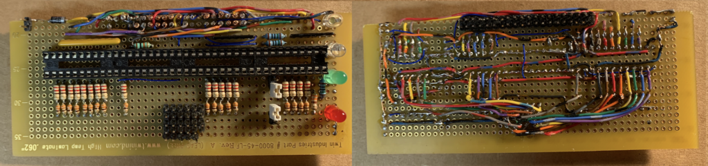
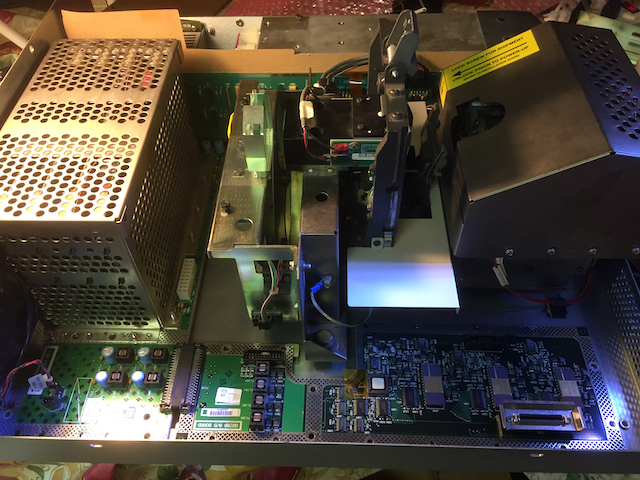
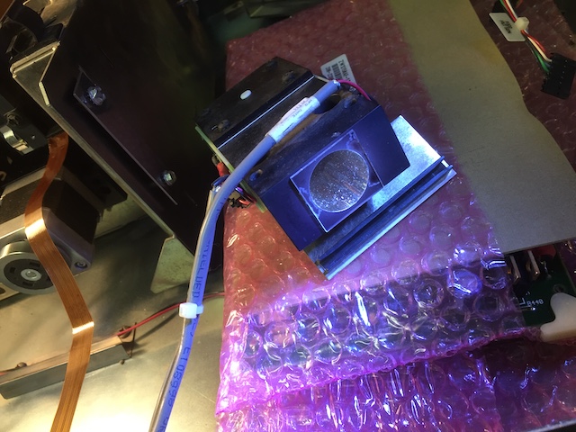
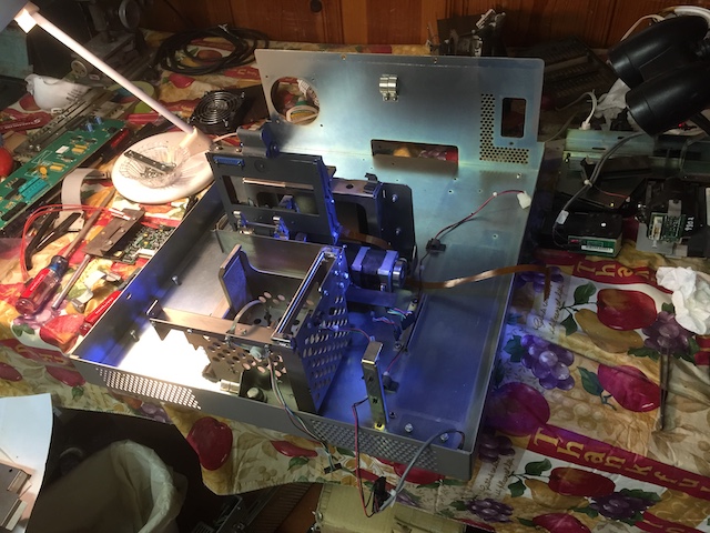
Having constructed a piscsi from used pipe organ relay parts I decided to take another look at some of the disk images I have aquired over the years. When I got the scanner in 2020 one reader of this blog was able to make available some salvaged backups of PCD 4050 data.
While the Cinion shared hardware with PCD the color model was completly different. Cineon favoring the recording of Dye densities. The focus on archiving cine camera negatives for transfer to laser based printing machines. The PCD was aimed at making things look good with the NTSC phosphors or CMYK prepress. Most writing on these subjects note that these models are mutually exclusive. One book even went as far as noting that this would be part of the solution of unified field theory in physics. Basically my take on this is relating color time and gravity. Colors are frequencies after all.
The data was salvaged by Maurice Schechter, who did not have much of an online presence. The main archive was called 4050_mac_os9.zip Also found was a file 4050.ZIP and something called 4050_1. 4050.Zip decompresses to about 450MB and 4051_1 is around 100MB. This is a fair amount of data. Maurice indicated he did not have anything else.
The service diagnostic programs had no resource forks. (they can be coaxed to run with stub resource forks, which is another area of study.)
The two zip files turned out to be bit identical. This appears to have been created with a unix zip tool as the creator file system is specified to be UNIX. There are no hidden resource files on either.
The file 4050_1 file appears to be compressed. It may have had a .sea suffix. The Stuffit command indicates it is not a sit file.

Apple dropped support for HFS disk images, which lead me to write an extractor for Diskcopy images what lost their resource forks. I had ported gzip and more importantly gunzip to mac OS7 in the 1990s to support building ghostscript on that system. Using MPW and A cobbled together X11 library that used quickdraw. A variation of this remains hidden here on some forgotten pages here https:www.delectra.com/tina MATLAB and openCV pretty much replaced this tool in computer vision research.
Apple diskcopy used a compression called ADC. It is evident that 4050_1 is not ADC as this compression uses LZ windowing to remove long runs (mostly empty disks sectors.) Text files retain large sections of readable chunks.
Sit files also contain a bit of text in the header and footer of the archive. Typically examples of these have file headers which contain the file name in plaintext.
Postscript has built in LZW and Flate (zlib) decoders. The 4050 data is not formatted for this either.
The first block of the 4050 file looks like this as a hex string represented in postscript:
/dBlock <
8F1A000627D3BAFD2B24726F5023F2F7
1F285005080FD3C00418D5E0047E0023
60A00D5FA7BE20B2E4D15E97F7827E8D
7D2BC990B057B3AF8C099BBE5E5C921C
FCFBDACE3DCD1B701385794E7BD9C434
718B536892457CFD0E2DBACA1AC25844
0804BF22AD423057C7532686B17FB98C
3491FF46C17E8DCFD971EC1D76ECF102
B5C2D9437ED0E65E8B73795DE84F3149
89B0DC418A07404A3D8159522DC64C03
5827731FAB5338C1CCA75A250EAA588D
ACC244C46DD4C422F95BCC64F45785D2
968CCC23C0C2C3B156D3243E674915DB
C5F0079FD966DE5F8A98595FDF7A11B5
83747836C1CFFCF9513C76336D8918BD
BBD9E2167480E2A61594409301E3FE35
D2F0C658C235C58934CB827684644242
06E6D4FCC540F54FF23BA66893F1301A
1E2AE5B9C8A244EA9F321C6E5E7284A3
1C16CB88E97F16FC8033A262ADBB64E1
FCE00337C0E38B062A30A01B80E6AC94
57937992A3D69D5605188488489E06DC
31026C00EEC7F98DFB921AD03B822C3D
EBFDE54453F960A59CF04A4900A6EB4F
C395EB2F51AB3B88604F68008F9C3132
004C9796B0A9575D70201D164F4F6F01
715A02E92D8037EAD9787BE38BD865C0
5A62FF8CF0AA10E7B99B536CE15C3613
1AFE27624F6994D0E7FAC4102040B041
24EA59201BFB86941F60D83701769092
023F6D94A960D7CDE7113E8034574498
22FB9203A2F074576D44BE05A1546602
> def
0x8F51 or 0x1A8F are no known magic cookies.
With the PISCSI I can mount the old versions of Stuffit and CompactPro (Compactor) Both wrote .sea archives. Many of the Kodak data fragments are in these formats. CompactPro also used the suffix .cpt These are Huffman coded compressions. Again there are no directories or magic cookies in this 100 megabytes of data.
As expected the mac port of zip (which supported resource forks) does not find any forks in the 4050.ZIP data.
There is a possibility this was compresses with a unix tool. pack and compress being likely candidates. Bzip2 is a bit modern for these archives, which were made before 2008. The archived data being from 1991 through 2003 or so.
So begins the waste of time doing another deep dive into LZ and Huffman using postscript.
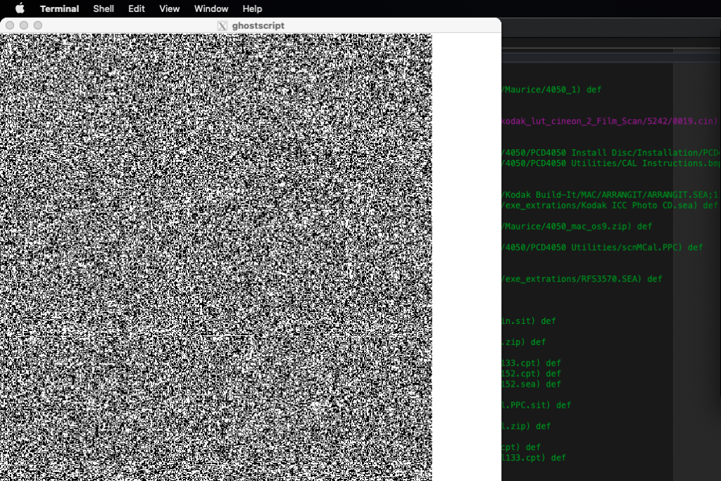
One way of looking at a disk sector image dump is to look at it as a bitmap of graphics. (File Allocation tables are often bitmaps.) Image data also can be disconcerted this way.
The easiest way is to dump one sector as a line of bits. Postscript makes this easy.
It can be seen that the data is pretty random.
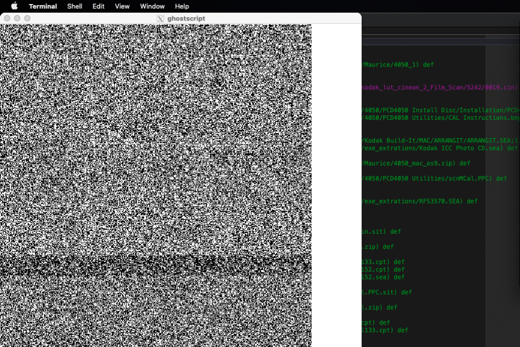
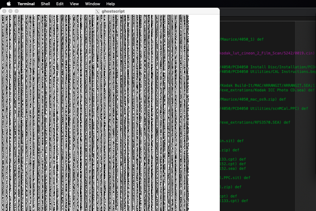
Since we now have the piSCSI and the lombard laptop, we can compress the interesting files with the popular sit and cpq compressors of the late 1990s, which return similar looking results.
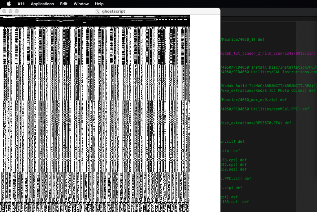
Paging through megabytes of data patterns start to emerge. Each page is about 50K of data.
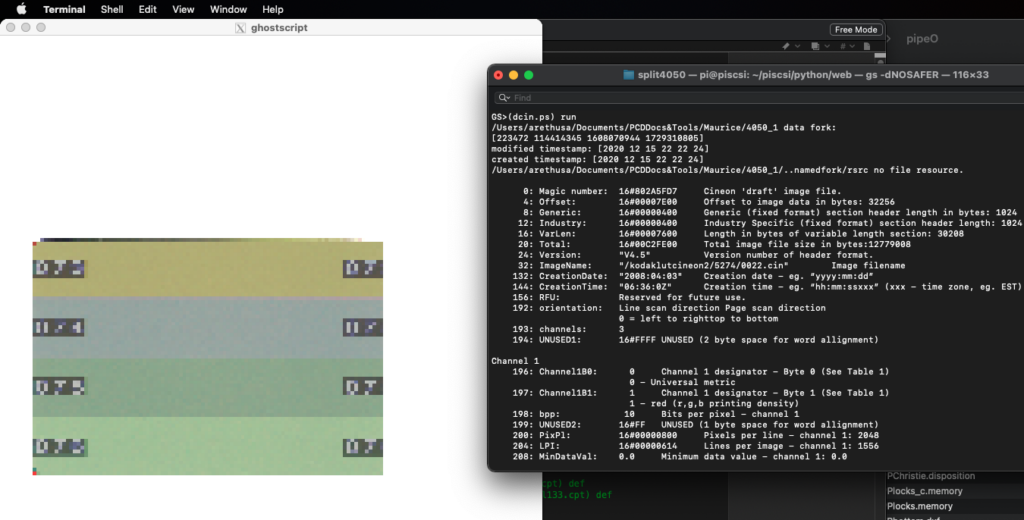
About a quarter of the way through the data changes patterns abrupbly. A huge runs of mark data. Looking at this data there is a pathname. ‘/kodaklutcineon2/5242/0019.cin’ This is followed by highly structured data what looks like ‘The Matrix.’ Almost like hieroglyphics or one of the asian character sets.
Looking at the first few bytes of the sector we have a magic number hit! This is an uncompressed cineon file!
By chance I also have a folder of these lut files. Not sure where they came from. The dates says I got them in 2020. The folder clocks in at over a gigabyte. Each lut is 13MB in size. A search also finds a draft PDF on this file format.
A quick write of a postscript program and we can dump the header. (see the teaser at the top of this blog.)
/Users/arethusa/Documents/PCDDocs&Tools/Maurice/4050_1 data fork:
[223472 114414345 1608070944 1729310805]
modified timestamp: [2020 12 15 22 22 24]
created timestamp: [2020 12 15 22 22 24]
/Users/arethusa/Documents/PCDDocs&Tools/Maurice/4050_1/..namedfork/rsrc no file resource.
0: Magic number: 16#802A5FD7 Cineon ‘draft’ image file.
4: Offset: 16#00007E00 Offset to image data in bytes: 32256
8: Generic: 16#00000400 Generic (fixed format) section header length in bytes: 1024
12: Industry: 16#00000400 Industry Specific (fixed format) section header length: 1024
16: VarLen: 16#00007600 Length in bytes of variable length section: 30208
20: Total: 16#00C2FE00 Total image file size in bytes:12779008
24: Version: “V4.5” Version number of header format.
32: ImageName: “/kodaklutcineon2/5274/0022.cin” Image filename
132: CreationDate: “2008:04:03” Creation date – eg. “yyyy:mm:dd”
144: CreationTime: “06:36:0Z” Creation time – eg. “hh:mm:ssxxx” (xxx – time zone, eg. EST)
156: RFU: Reserved for future use.
192: orientation: Line scan direction Page scan direction
0 = left to righttop to bottom
193: channels: 3
194: UNUSED1: 16#FFFF UNUSED (2 byte space for word allignment)
Channel 1
196: Channel1B0: 0 Channel 1 designator – Byte 0 (See Table 1)
0 – Universal metric
197: Channel1B1: 1 Channel 1 designator – Byte 1 (See Table 1)
1 – red (r,g,b printing density)
198: bpp: 10 Bits per pixel – channel 1
199: UNUSED2: 16#FF UNUSED (1 byte space for word allignment)
200: PixPl: 16#00000800 Pixels per line – channel 1: 2048
204: LPI: 16#00000614 Lines per image – channel 1: 1556
208: MinDataVal: 0.0 Minimum data value – channel 1: 0.0
212: MinQuantity: 0.0 Minimum quantity represented – channel 1: 0.0
216: MaxDataVal: 1023.0 Maximum data value – channel 1: 1023.0
220: MaxQuantity: 2.047 Maximum quantity represented – channel 1: 2.047
Channel 2
224: Channel1B0: 0 Channel 2 designator – Byte 0 (See Table 1)
0 – Universal metric
225: Channel1B1: 2 Channel 2 designator – Byte 1 (See Table 1)
2 – green (r,g,b printing density)
226: bpp: 10 Bits per pixel – channel 2
227: UNUSED2: 16#FF UNUSED (1 byte space for word allignment)
228: PixPl: 16#00000800 Pixels per line – channel 2: 2048
232: LPI: 16#00000614 Lines per image – channel 2: 1556
236: MinDataVal: 0.0 Minimum data value – channel 2: 0.0
240: MinQuantity: 0.0 Minimum quantity represented – channel 2: 0.0
244: MaxDataVal: 1023.0 Maximum data value – channel 2: 1023.0
248: MaxQuantity: 2.047 Maximum quantity represented – channel 2: 2.047
Channel 3
252: Channel1B0: 0 Channel 3 designator – Byte 0 (See Table 1)
0 – Universal metric
253: Channel1B1: 3 Channel 3 designator – Byte 1 (See Table 1)
3 – blue (r,g,b printing density)
254: bpp: 10 Bits per pixel – channel 3
255: UNUSED2: 16#FF UNUSED (1 byte space for word allignment)
256: PixPl: 16#00000800 Pixels per line – channel 3: 2048
260: LPI: 16#00000614 Lines per image – channel 3: 1556
264: MinDataVal: 0.0 Minimum data value – channel 3: 0.0
268: MinQuantity: 0.0 Minimum quantity represented – channel 3: 0.0
272: MaxDataVal: 1023.0 Maximum data value – channel 3: 1023.0
276: MaxQuantity: 2.047 Maximum quantity represented – channel 3: 2.047
Channel 4
280: Channel1B0: 255 Channel 4 designator – Byte 0 (See Table 1)
255vendor specific
Vendor defined
281: Channel1B1: 255 Channel 4 designator – Byte 1 (See Table 1)
255 – Vendor defined
282: bpp: 255 Bits per pixel – channel 4
283: UNUSED2: 16#FF UNUSED (1 byte space for word allignment)
284: PixPl: 16#FFFFFFFF Pixels per line – channel 4: 4294967295
288: LPI: 16#FFFFFFFF Lines per image – channel 4: 4294967295
292: MinDataVal: 0.0 Minimum data value – channel 4: 0.0
296: MinQuantity: 0.0 Minimum quantity represented – channel 4: 0.0
300: MaxDataVal: 0.0 Maximum data value – channel 4: 0.0
304: MaxQuantity: 0.0 Maximum quantity represented – channel 4: 0.0
Channel 5
308: Channel1B0: 255 Channel 5 designator – Byte 0 (See Table 1)
255vendor specific
Vendor defined
309: Channel1B1: 255 Channel 5 designator – Byte 1 (See Table 1)
255 – Vendor defined
310: bpp: 255 Bits per pixel – channel 5
311: UNUSED2: 16#FF UNUSED (1 byte space for word allignment)
312: PixPl: 16#FFFFFFFF Pixels per line – channel 5: 4294967295
316: LPI: 16#FFFFFFFF Lines per image – channel 5: 4294967295
320: MinDataVal: 0.0 Minimum data value – channel 5: 0.0
324: MinQuantity: 0.0 Minimum quantity represented – channel 5: 0.0
328: MaxDataVal: 0.0 Maximum data value – channel 5: 0.0
332: MaxQuantity: 0.0 Maximum quantity represented – channel 5: 0.0
Channel 6
336: Channel1B0: 255 Channel 6 designator – Byte 0 (See Table 1)
255vendor specific
Vendor defined
337: Channel1B1: 255 Channel 6 designator – Byte 1 (See Table 1)
255 – Vendor defined
338: bpp: 255 Bits per pixel – channel 6
339: UNUSED2: 16#FF UNUSED (1 byte space for word allignment)
340: PixPl: 16#FFFFFFFF Pixels per line – channel 6: 4294967295
344: LPI: 16#FFFFFFFF Lines per image – channel 6: 4294967295
348: MinDataVal: 0.0 Minimum data value – channel 6: 0.0
352: MinQuantity: 0.0 Minimum quantity represented – channel 6: 0.0
356: MaxDataVal: 0.0 Maximum data value – channel 6: 0.0
360: MaxQuantity: 0.0 Maximum quantity represented – channel 6: 0.0
Channel 7
364: Channel1B0: 255 Channel 7 designator – Byte 0 (See Table 1)
255vendor specific
Vendor defined
365: Channel1B1: 255 Channel 7 designator – Byte 1 (See Table 1)
255 – Vendor defined
366: bpp: 255 Bits per pixel – channel 7
367: UNUSED2: 16#FF UNUSED (1 byte space for word allignment)
368: PixPl: 16#FFFFFFFF Pixels per line – channel 7: 4294967295
372: LPI: 16#FFFFFFFF Lines per image – channel 7: 4294967295
376: MinDataVal: 0.0 Minimum data value – channel 7: 0.0
380: MinQuantity: 0.0 Minimum quantity represented – channel 7: 0.0
384: MaxDataVal: 0.0 Maximum data value – channel 7: 0.0
388: MaxQuantity: 0.0 Maximum quantity represented – channel 7: 0.0
Channel 8
392: Channel1B0: 255 Channel 8 designator – Byte 0 (See Table 1)
255vendor specific
Vendor defined
393: Channel1B1: 255 Channel 8 designator – Byte 1 (See Table 1)
255 – Vendor defined
394: bpp: 255 Bits per pixel – channel 8
395: UNUSED2: 16#FF UNUSED (1 byte space for word allignment)
396: PixPl: 16#FFFFFFFF Pixels per line – channel 8: 4294967295
400: LPI: 16#FFFFFFFF Lines per image – channel 8: 4294967295
404: MinDataVal: 0.0 Minimum data value – channel 8: 0.0
408: MinQuantity: 0.0 Minimum quantity represented – channel 8: 0.0
412: MaxDataVal: 0.0 Maximum data value – channel 8: 0.0
416: MaxQuantity: 0.0 Maximum quantity represented – channel 8: 0.0
420: WhitePoint: <3EAA30553EB1DE6A>> White point (color temperature) – x,y pair: [0.3324 0.3474]
428: RedPrimary: <7F8000007F800000>> Red primary chromaticity – x,y pair: [0.0 0.0]
436: GreenPrimary: <7F8000007F800000>> Green primary chromaticity – x,y pair: [0.0 0.0]
444: BluePrimary: <7F8000007F800000>> Blue primary chromaticity – x,y pair: [0.0 0.0]
452: LabelText: “”
652: RFU2: Reserved for future use.
Image Data Format Information :
680: DataInterleave: 0 = pixel interleave (rgbrgbrgb…)
681: Packing: 5 = longword (32 bit) boundaries – left justified
682: SignedData: 0 = unsigned
683: ImageSense: 0 = positive image
684: EOLPad: 16#00000000 End of line padding – number of bytes.
688: EOC: 16#00000000 End of channel padding – number of bytes.
692: RFU3: Reserved for future use.
Image Origination Information :
712: XOffset: 16#00000000 correlate digital data to source media.
716: YOffset: 16#00000000 correlate digital data to source media.
720: ImageName2: /kodaklutcineon2/5274/0022.cin
820: CreationDate2: 2008:04:03 Creation date – eg. “yyyy:mm:dd”
832: CreationTime2: 06:36:0Z Creation time – eg. “hh:mm:ssxxx” (xxx – time zone, eg. EST)
844: InputDevice: “GenesisPlus:MP35mm”
908: ModelNumber: “35mm”
940: SerialNumber: “361”
972: XdevicePitch: 166.667 X input device pitch (samples/mm.)
976: YdevicePitch: 166.667 Y input device pitch (samples/mm.)
980: CDGamma: 0.0 Image gamma of capture device.
984: RFU4: Reserved for future use.
Section 2 – Motion Picture Industry Specific (Fixed Format) :
1024: MFGIDcode: 255 Film mfg. ID code – 2 digit code from KEYKODE
1025: FilmType: 255 Film type – 2 digit code from KEYKODE
1026: PerfOffset: 255 Offset in perfs – 2 digit code from KEYKODE
1027: UNUSED3: 16#FF 1 byte space for word allignment
1028: Prefix: 16#FFFFFFFF – 6 digit code from KEYKODE: 4294967295
1032: FlCount: 16#FFFFFFFF Count – 4 digit code from KEYKODE: 4294967295
1036: Format: “” Format – eg. “ACADEMY, ”VISTAVISION“, etc.
1068: FramePosition: 16#00000016 Frame position in sequence 22
1072: FrameRate: 0.0 Frame rate of original (frames per second)
1076: FrAttribute: “” Frame attribute – eg. “KEYFRAME”
1108: Slate: “” Slate information
1308: RFU5: Reserved for future use.
Section 3 – User Defined (Variable Length) :
2048: VarLen: 30208
05D66580: 97936768
>>showpage, press to continue<<
A search of the 4050_1 archive finds 7 of these files. Which take up nearly 3 quarters of the archive.
Yet an issue remains. One of the files is fragmented. The next header is 10MB in the middle of it.
So this could still be a disk image archive. 12MB files were ginormous in the 1990s. They ate disk space. Compressors would choke on them
There is a strong possibility 4050_1 archive is part of a multi volume archive. Typically though these have headers so they can be stitched together.
The first 22MB still contains high entropy data. Which triggered more time wasting to go yet again through a deep dive of huffman lz coding to see if any patterns can be found.
The notes are not too encouraging. Where are the magic cookies? What arcane program was left to compress this archive.
At least I have a bunch of postscript tools for reading disk images which I can upload to github. Not sure though that can take gigabytes of archive data. Not really shure what can. Most people are more interested in mining it. (which in a way is what I am doing.)
Since these tools may be of interest I uploaded this to github under the name sheepdoll.
https://github.com/sheepdoll/PSDiskImageArchiveTools
This blog forms an early dratf of the readme as I had to upload there first before having a place to link to.
Postscript makes it easy to dump and format hex data, even binary. Here are some results from the command line. Looking at this seems much a waste of time, even if there is data there, is it worth the time searching for it.
% 8F 1A 00 06 27 D3 BA FD 2B 24 72 6F 50 23 F2 F7 1F 28 50 05 08 0F D3 C0 04 18 D5 E0 04 7E 00 23

% 1000 1111 0001 1010 0000 0110 0010 0111 1101 0011 1011 1010 1111 1101 0010 1011 0010 0100 0111 0010

% 100011110 001101000 000110001 001111101 001110111 010111111 010010101 100100100 01110010
% 286 104 49 125
% 11E 064 031 07D 077 0BF 095 124


% 10001111 000110100 000011000 100111110 100111011 101011111 101001010 110010010 001110010
% 8F 034 018 13E 13B 15F 14A 192 072

% 1A8F 0600 D327 FDBA 242B 6F72 2350 F7F2 281F

% 0001 1010 1000 111 0110 0000 1101 0011 0010 1110 1111 1101

% 000110101 000111011 000001101 001100101 11011111 101
% 035 03B 00D 065 1BF

% 876543210 876543210 876543210 876543210 876543210 876543210 876543210 876543210 876543210
% 765432107 654321076 543210765 432107654 321076543 210765432 107654321 076543210 765432107
% <<1 <<2 <<3 <<4 <<5 <<6 <<7
% mmmmmmmm mmmmmmm mmmmmm mmmmm mmmm mmm mm m
% M MM MMM MMMM MMMMM MMMMMM MMMMMMM MMMMMMMM


% mac cpt packit/compactor in dcpt base values out of range -- and this looked so promising


%banana.z
%/of (banana.z) (w) file def
%of <1f1e0000000603010100616e6216c8> writestring
%of closefile


% pack -- not promising
% /*
% * check two-byte header --------> !fails here obviously 1F1E 1F9D is compress
% * get size of original file, -------> 6 or 1536 if long could be 403411
%orig size long 27d3ba 2610106 invalid
% * get number of levels in maxlev, -----> short invalid 6, 27
% * get number of leaves on level i in intnodes[i], 211 -- nodes are short -- looks invalid
% * set tree[i] to point to leaves for level i
% */


% packbits

% 8F 1A 00 06 27 D3 BA FD 2B 24 72 6F 50 23 F2 F7 1F 28 50 05 08 0F D3 C0 04 18 D5 E0 04 7E 00 23
% ^ ^ ^ ^ ^
% | | | | |
% | | | | |
% | | | | +--- 72 bytes of litteral dat -- probably not packbits
% | | | +--- 6 bytes of litteral data <27 D3 BA FD 2B 24>
% | | +----- zero
% | +----- data to repeat
% +-- run 16 1A


% ADC checked in ddskcpy/ddskimg and filterws.ps -- typically adc sliding window leaves bits and pecies of
% readable text