

Some years ago I was given a UM1 that had the logic supply connected to enough voltage to crack the power regulator. Most likely every chip was blown apart.
I had used a similar processor for a video conversion project, which has long sat documented in the video section of my website, an early form of blogging from the late 1990s. I still had a tube of these processors, although the ones I had were 52 pins, where the processor on the um1 had 44 pins.
Since I frequent the surplus shops of the silicon valley, I located most of the chips used in this board. Given supply issues, I have for other clients developed a similar board using a more modern embedded micro. More on this in a later blog. The short version is that I had a UM0 and wanted to keep the same setup codes and configuration on my Caliola.
By connecting a MIDI sniffer to the wire, I was able to detail how the setup system exclusive messages worked. Technically these are supposed to be documented in the manual. The manufacture is not registered so the device setup for these exclusives is the research mark. Which means that this data is open and unprotected, so I could use it.
I noticed that the Octet setup program had a mechanism for uploading new firmware updates. These updates were available on the web. When opened they were found to be in the common format used by the MC68HC11. There was even included a small program called a talker.
Locating the needed chips, the question remained, would it be possible to reprogram the actual UM1 unit from the web updates?
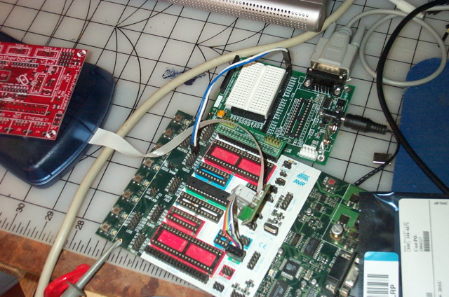
The first step of the process was to remove all the old chips. This was done with a heat gun. The board is slowly heated to 210degrees C. My thermocouple slipped and some of the sockets got a little cooked, the result was a clean board. The front panel was the worse for wear as the switches melted completely.
After the chips were removed, the traces were cleaned up and documented with the Eagle layout program. Oh for the days of Sam’s Photofacts. I wonder if the library still has the shelves of 1950s and 1960s era television schematics. Actually I was able to get schematics for my late 1990s Panasonic, telly. So major manufactures do still provide repair personnel this needed information.
The designer of the UM1 had been dead for some decades now. The successor does provide manuals and firmware files as noted. I took a peek inside these files and located where the device tables go. In order to bring a new system up from scratch, a few additional items such as the serial number are needed. This was easy to get, as it was pasted onto the blown up chip. The firmware for some reason does not contain the device string, which for some reason is always UM1 even on a UM0.
I was a bit concerned that I would have to solder in the new processor. These are surprisingly still available. This package called a PLCC is no longer made. When the EU adopted RoHS this format was discontinued. In the surplus store I was able to find a socket that would solder onto the board, so anyone in the future who needs to fix this can swap the chip out.
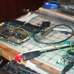
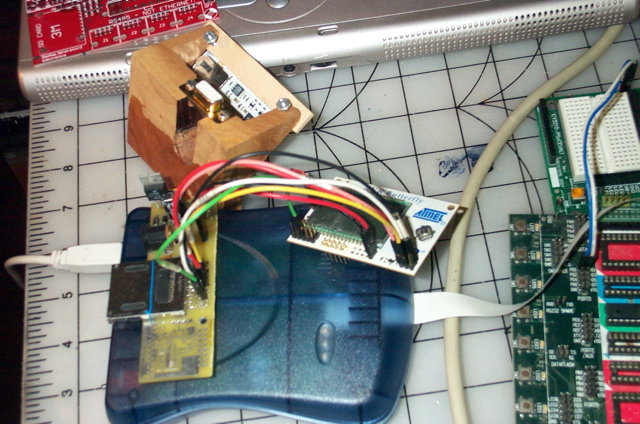
Once the new chips were in place it was time to reprogram the unit. I could have connected in through the MIDI interface. The 68HC11 contains a serial boot mode. There is a photograph of this in the attached image gallery. These signals are easy to access on the 74HC02 chip labeled U9. For future reference the pins are Rx on pin 8 and Tx on pin 6. Laurent must have used jbug as the wiring of these pins is straight out of the college textbooks.
The 68HC11D0 contains no internal flash memory. It is easy from looking at the schematic, to see where the memory starts. 0x2000. This is where the jbug11 talker is loaded. The firmware loads in at 0xE000. This is where the SYSEX tables are stored.
The first step is to upload the firmware from the website or setup disks(If available) This can be uploaded by simply renaming the file extension from .frm to .s19. Since the firmware does not overwirte the device information, this will need to be copied from a working UM1 The format is exactly the same as what the UM0/UM1 setup software sends, so this can simply be done by dumping the read firmware sysex
Once this data is written to the first sector of the 0xE000 address, there should be enough code to get the whole unit working. In my case I replaced the MIDI opo-isolator and the U9 74HC02 chip. I was able to connect using the Octet setup program. Just to be safe I re-ran the firmware upgrade.
It should be obvious that a working UMx is needed to get things stared, this blog is about repairing units. There are much better and cheaper ways to make similar devices, which is why my own boards are only functionally equivalent, with no common hardware.
Naturally the diagnostics did not pass as I had not seated in the driver chips. These are often out of stock and I had to get some from other units for testing. Once installed, The diagnostics pass muster and the unit is once more operational apart from a missing chip for the PWM and the melted front panel. The UM1 works fine without the front panel, but there are some unsightly holes where it goes.
Repairing the front panel did not have quite the same success. I socketed these chips, which means the display plate no longer fits. The surplus hex switches are also much larger and do not have the same pinout, so give the wrong midi channel. There is also quite a bit of flicker on the LeDs. Most of these units are set once anyway, so the front panel is a nice extra, but not needed.
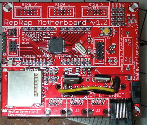
It is interesting to compare my “clean room” copy to the original. There is no hardware in common. I do parse some of the same setup code which is what makes my unit a clone.
The repair on this is also quite expensive, The obsolete processor sells for 10s of dollars, when in stock. [Currently at this I have some similar E2 processors for sale on eBay]. Atmel processors sell for a few dollars each, These contain many times the storage space and do not need the external logic. The replacement parts on the UM1 were around 35 dollars not counting the driver chips. It probably would be cheaper to buy a new unit, if such were available.
Over the next few months, I expect to sell some of my compatible prototypes online. I much prefer consulting and building devices to order. I also am willing to take on repair of the octet systems as well as any Broadmore power rolls that may still exist.


 This is an interesting way of making a gasket. I am not sure if this is the best place for this method, but it seems worth a try. This is how Wurlitzer gaskets the regulators to the wind trunks.
  Finally we show the progress. All the main parts are in place and mounted to the sides. I did get a sheet of MDF for the pipe rack. Not sure when I will have time to cut it. I may just mount the pipes onto thin strips of board (I have a lot of that material.)