Twenty first century SCSI

It has been a year since I last worked much with the Kodak PCD film scanner. Having reverse engineered the bulk of the photoshop plugin and diagnostic code, It was time to start working with hardware.
The PCD 2000 scanner uses a smaller SCSI 50 contact connector. These do not turn up in e-Waste bins often. More common are the wide 68 pin connector used in server installations.
Modern systems do not have SCSI, although parts of the standard live on in USB sticks and smart memory cards. It is hard to find physical drives so project like RPSCSI forked as PISCSI make for a nice way of connecting to old devices. These tend to focus on drives, with little or no provisions for scanners. Printers seem to remain on the wishlist.
Probably the simplest thing would be to simply make an adapter cable for the scanner. Since the scanner weighs 60 or 70 pounds, it is not all that practical to move it onto the table. It also takes up a lot of space.
The Kodak software trends from several different collections. The easiest to find is the update to the photoshop plugin. This is missing a number of support install files and librarys. A backup of a complete OSX 8.1 system had been made, but was zipped which removed all the missing resource fork metadata. Investigation showed the code was written in CodeWarror. This allows the plugin to be re constituted, although the Kodak Color matching profiles remain missing.
The code was built with debug symbold (mangled C++ names) so the disassembly is fairly easy to read. The bulk of the code using Powerplant librarys, for which source code exists. Some of the other libraries were used with the SUN based workstation. This was used in situ in the macintosh port.
Thanks to readers of this blog the zipped archive, and Installer disks for the SUN based workstation were found. The Solaris PIW could probably be reverse engineered, however the same code base was used for the Macintosh plugin.
The plugin however was only written to support the 4050 scanner. Not the 2000 It does run to the point where a SCSI system inquiry is sent.
More interesting on the backup Zipped drive folder were diagnostic programs. These were built from the same code base as the Photoshop plugin. Unlike that system the metadata is completely missing. This includes the methods for creating and drawing the user interface windows.
The compilers are available on many of the vintage computer websites. So It is possible to use the UI design tool and some of the method names to create a stub application and re-create the UI windows. This metadata though is created progametrically, so some menu actions are not sent to the handlers. Or it is difficult to match handler methods to missing window entities which use inherited class properties. Still it is enough to reconstruct the code to manually jump through the main dispatch loop to the code what handles the sub windows.
Like the photoshop plugin, the diagnostic program sends a SCSI inquiry, the exits.
Since I only have a Filmscanner2000, it seems for tracing it would be better to spoof the inquiry to look like the 4050. This has a number of benefits. Namely that the code can be run without modification. There are hints that the 2000 and even the 1000 scanner can be detected. At least to warn the user that the wrong scanner is selected.
A lot of the diagnostic and photoshop plugin code seems to be there to emulate a UNIX style device tree. The preferences data missing from the Photoshop pluging consists of dozens of often single line text files which outline the device tree database. This data was not stored in the resource fork, so it remained on the 8.1 zipped image.
Another reader sent scans of the PCD service documents and calibration film strips. This has been a great wealth of information. I have been using makerspace laser cutters to cut out templates and fixtures.
I also got deep into APS film format and located the main technical specs, which include dimentions, how to read the magnetic codes and the bar codes on the film an canisters. A side project which has taken a lot of time is to work out how to cut down fresh 35mm film. Too bad one can not use the laser to cut the film as that would be easy. Hopefully it will not be so long before the next blog.
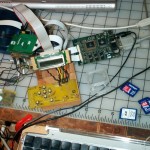
Meanwhile I found more useful hardware and returned to the scanner driver.
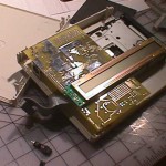
The vintage macs with SCSI ports I have access to are G3 based, a wallstreet, and more recently a lombard. found in eWaste for 15 bucks USD. The lombard had a bad HD cable. Using a DVD drive bay adapter a hard drive could be added. Although at the cost of the seldom used DVD slot. This makes a great backup system for experimentation.
By chance I still have an Apple ColorOne Scanner, and the adapter cable. Before finding this plan was to use a laser cutter to make a direct adapter. I did locate a minature 50 pin SCSI cable when I got the PCD scanner. I promptly cut this in half to make an adapter. For some reason ringing out the 50 connectors which are not in phone cable color order lead to a lot of procrastination. The ida was to jam these wires into the back of the MAC SCSI port. These cable halfs sat in the box of scanner parts for the last thee years.
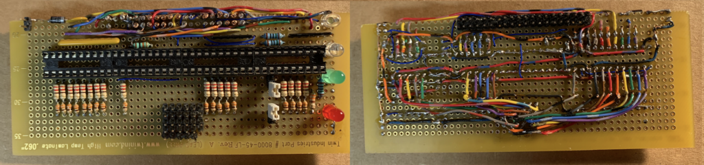
While I could simply get a PISCSI, I realized I do have most of the parts needed. Jameco sells the buffer chips in DIP packages. So I orderd a short tube of them. Ringing out the cable shows that the wires use the resistor (or ribbon) color code with 12 colors. I think the remaining colors are known as Salmon (pink), Aqua and Teal. The traces are white black and red.
Tracing the cable showed how simple SCSI really is. There are really only 18 signals used. The rest are grounds and pair returns. Which is how Apple was able to use 25 or 30 pin connectors.
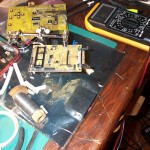
Pipe organs also often use 50 pin connectors. I had a few of these left over from scrapping out a S’n’DelCo relay. I also had some copper foil tape left over from a stained glass class I took some 50 years or so back. This occasional was used for pipe organ return bus. Some of this got upgraded, but still had some sticktivity to it. I also have Kapton tape and the friction tape used to wrap the cable.
Using a guide to SCSI cables, I decided then to make a shielded cable, with the signals isolated into layers. I retained the same pattern as the laptop connector rather than the DB25. The pitch however is not the same.
This in turn is the ultimate recycling as some of the items I have had for up to 50 years.
I also learned how to connect the Pi Zero to the 10.4 tiger as a headless dongle and bridge it to the network using the Ethernet Gadget. No more messy USB hubs, monitors and keyboards. This makes the Zero feel much more like an arduino or STM32F4 Nucleo.
Getting the Ethernet Gadget to work under osz 10.4 ‘Tiger’ was a bit of a challenge as the networking bridge was not included, and had to be compiled. These old war horses do not connect gracefully to the net. Fortunately someone a decade ago did create a fork of the commonly used driver. The git pulls and configuration scripts needing to be run on a separate connected machine first.
There is still a lot to do. Most of the focus on the PISCSI is as a turnkey product. So the internal documentation is sparse. The development focus seems to be more directed to the web interface.